Any AVR microcontroller based board which follows the standard Arduino schematic and is flashed with the Arduino boot-loader can be called an Arduino board. The Arduino is an easy prototyping platform in which the hardware is very simple to use and to be connected with any other system. The programing environment is also very easy to start with and has lot of built-in functions for every simple and complex task.
The interrupt is a method by which a microcontroller is made to divert from current path of code execution to do some other important things that needs immediate processing. The code which is written to process whenever an interrupt occurs is called an Interrupt Service Routine (ISR). Once an interrupt occurs the controller stops its current processing and start executing the ISR. This project demonstrates how to use the external interrupt pin of an Arduino board by changing the status of an LED each time the interrupt occurs.
This article discusses the external interrupt based on the Arduino pro-mini board which is programmed using the Arduino IDE version 1.0.3 downloaded for windows. The advantage of this board is that it comes in very small in size; different kind of connectors can be soldered according to the application requirements. It is very breadboard friendly and occupies very less space of a typical breadboard. The board also provides two external interrupt pins.
The image of the Arduino pro-mini board and the screen shot of the Arduino IDE are shown below;

Fig. 2: Typical Arduino Pro-Mini Board

Fig. 3: Arduino IDE Software Window
Since the arduino pro-mini board has no circuitary for interfacing it with the serial port or the USB port of the PC, an external USB to TTL converter board is required to connect it with the PC. This hardware helps in programming the arduino board and also helps in the serial communication with the PC through the USB port of the PC.

Fig. 4: External USB to TTL converter board for programming Arduino and serial communication
It is assumed that the reader has gone through the project how to get started with the arduino and done all the things discussed in it.
Interrupt occurs when the pin is connected to a low valued voltage (low voltage triggered)
Interrupt occurs when voltage at the pin changes from high value to a low value (falling edge triggered)
Interrupt occurs when voltage at the pin changes from low value to high value (rising edge triggered)
Interrupt occurs whenever the voltage transition occurs at the pin i.e. interrupt for both low to high and high to low transitions (state change triggered)
The interrupt pins are usually connected with pull-up or pull-down resistors depending on the triggering method used by the interrupt pin. The pull-up resistor is used when the pin uses low voltage triggering or falling edge triggering. The pull-down resistors are used when the interrupt pin uses rising edge triggering. The project uses rising edge triggering and the triggering circuitry is very simple using a push button and a pull down resistor of value 10K. The Arduino IDE provides some functions to make use of the interrupt features of the Arduino board. The code written for this project make use of functions attachInterrupt() and detachInterrupt() which can be used to enable an interrupt on either of the two external interrupt pins or disable an already enabled interrupt respectively. The details of the functions are discussed in the following section;
attachInterrupt()
The function attachInterrupt() is used to enable an interrupt on either of the two external interrupt pins along with configuring the type of triggering and also assigning an ISR to be executed whenever an interrupt occurs. The function has three variables, the first one is the pin number at which the interrupt signals expected to appear and the second one is the function which can act as the ISR. The third parameter defines the method of triggering.
The prototype of the function is given as the following;
void attachInterrupt ( interrupt_pin, isr_function, trigger_method );
The return type of the function is declared as void and hence the function returns nothing. The first parameter is the interrupt pin which determines at which pin the interrupt should be enabled as mentioned below
– interrupt_pin
0 for enabling the interrupt on pin2
1 for enabling the interrupt on pin3
The second parameter points to the function which should be made as the ISR. The parameter should be provided with the name of the function which is required to act as an ISR.
The third parameter defines the kind of triggering that should be enabled on the interrupt pin mentioned by the first parameter. The four different values and their details that can be applied to the third parameter are given below;
– trigger_method
LOW to trigger the interrupt whenever the pin is low,
CHANGE to trigger the interrupt whenever the pin changes value
RISING to trigger when the pin goes from low to high,
FALLING for when the pin goes from high to low.
detachInterrupt()
The function detachInterrupt() is used to disable the interrupt on either of the interrupt pin at which the interrupt is already enable by the function attachInterrupt(). The function has no return value but one parameter which is the pin number on which the interrupt should be disabled.
For example to disable the interrupt on the pin number 2 one can use the following statement;
detachInterrupt(0);
To disable the interrupt on the pin number 3 one can use the following statement;
detachInterrupt(0);
THE CODE
The code initializes the pin number 6 as output at which an LED is connected using the function pinMode() and later in the code it continuously write a value to that particular pin using the function digitalWrite() which are already discussed in a previous project on how to get started with the Arduino.
The function attachInterrupt() is used to enable the interrupt on the pin number 2 with assigning an ISR function. The pin is configured as rising edge triggered. Each times an interrupt occurs the ISR inverts the value that is continuously written to the pin number 6. There is also a condition written inside the function loop() which will continuously check a count to become greater than 10 which is incremented inside the ISR. After 10 interrupts the condition becomes true and it disables the interrupt using the function detachInterrupt().
The code also displays some text on the LCD with the help of the functions from the library <LiquidCrystal.h>. The important functions provided by the library <LiquidCrystal.h> are already used and explained in previous projects on how to interface an LCD, how to display sensor value on LCD, how to connect the LCD with the PC and how to make an LCD scrolling display.
When the coding is finished one can verify and upload the code to the Arduino board as explained in the project how to get started with the Arduino. The interrupt can be triggered by pressing the push button which will make a low to high transition on the interrupt pin. The ISR runs each time the interrupt occurs and one can observe the LED changing its state from off state to on or from on state to off for the first ten key press.
Project Source Code
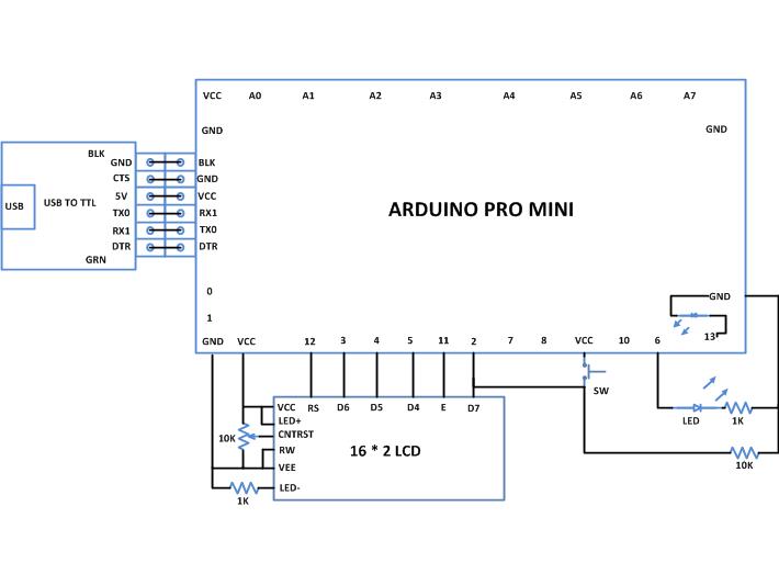
###


/*================================= EG LABS =======================================

Using an external interrupt to change the state of an LED

 The circuit:

 * LED attached from pin 6 to ground through a 1K resistor

 LCD:

 * LCD RS pin to digital pin 12

 * LCD Enable pin to digital pin 11

 * LCD D4 pin to digital pin 5

 * LCD D5 pin to digital pin 4

 * LCD D6 pin to digital pin 3

 * LCD D7 pin to digital pin 2

 * LCD R/W pin to ground

 * 10K resistor:

 * ends to +5V and ground

 * wiper to LCD pin 3

 * LED anode attached to digital output 6

 * LED cathode attached to ground through a 1K resistor

//================================= EG LABS =======================================*/

#include <LiquidCrystal.h>

LiquidCrystal lcd(12, 11, 5, 4, 3, 2);   // initialize the LCD library with the numbers of the interface pins

int led = 6;                                         // variable indicating the pin number where the LED is connected

int led_state = 0;                                   // variable indicating the state of the LED

int count = 0;

void setup()

{

  pinMode(led, OUTPUT);                              // initialize the digital pin as an output.

  lcd.begin(16, 2);                                  // set up the LCD

  lcd.print("ENGINEERS GARAGE");

  lcd.setCursor(0, 1);

  lcd.print("  EXT INTERRUPT ");

  delay(2000);

  lcd.clear();

  lcd.print("  EXT INTERRUPT ");

  lcd.setCursor(0, 1);

  lcd.print("     ENABLED    ");

  attachInterrupt(0, glow, RISING);                 // enable the external interrupt 0, with function 'glow' as ISR and interrupt occurs on rising edge

}

void loop()

{

  digitalWrite(led, led_state);                      // turn the LED on or off depending on the value of the 'led_state'

  if(count > 10)

  {

    detachInterrupt(0);

    lcd.setCursor(0, 1);

    lcd.print("    DISABLED    ");

  }else;

}

//========== ISR ============//

void glow()

{

  count ++;

  led_state = !led_state;                             // invert the value of the led_state

}

//========== ISR ============//

###
Circuit Diagrams
Project Components
Project Video
Filed Under: Arduino
Filed Under: Arduino

Questions related to this article?
👉Ask and discuss on Electro-Tech-Online.com and EDAboard.com forums.
Tell Us What You Think!!
You must be logged in to post a comment.