In this tutorial i am going to teach you how to increase(add) digital I/O (Input-Output) Pins of Arduino uno. Their are normally 14 (0-13) Digital Pins on Arduino & 6 (0-5) Analog pins on Arduino uno. Some times your application needs more digital pins than available on the Arduino board. For example you want to connect an lcd and a 4×4 keypad with arduino & you want to use lcd in 8-bit Mode. Now 14 pins are not enough to connect both the lcd and keypad with arduino. You need some extra pins to carry out the task.
LCD is comprised of 8 data pins and 3 control pins(rs,rw,en) Total 8+3=11. Keypad 4×4 contains 4 Rows and 4 Coulombs Total 4+4=8. Now for this scenario given above you need Total 11+8=19 Pins and arduino uno only have 12 digital input output pins. So we have to add some more pins to arduino.
Increasing digital I/O pins of Arduino – Solution
The best solution is to use 8255 chip with Arduino. 8255 is a Programmable Peripheral Interface. It comes in 40 Pin DIP Package. It has Three 8-bit Input-Output Ports A, B & C. Total I/O pins becomes 8×3=24. All The three ports can be used as I/O. Port A & B of 8255 can only be used as 8-bit input-Output Port. But Port C individual bits can be used as general purpose I/O pins. 8255 adds 24 new digital input output pins to arduino uno board.
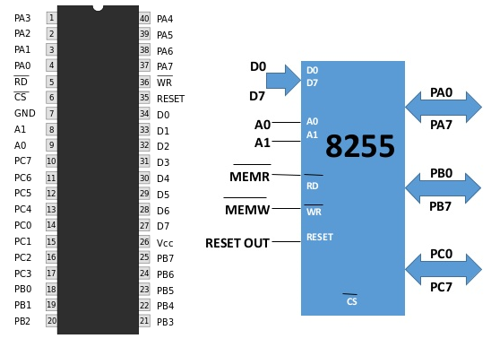
Intel 8255 PPI Pin out, ports and control pins
Full Description of the chip with control information is available in the link below. Its impossible to cover all of the aspects of 8255 here. So it is provided in an another tutorial. I recommend you to please go through the link other wise you can not understand the code below and interfacing of 8255 with arduino Microcontroller.
Increasing arduino digital pins with 8255 diy project
Lets start with a simple project on how to blink led’s by interfacing 8255 with arduino uno. Led’s are connected to Port-B of 8255 Chip. Port-A & C are not used here. Data pins of 8255 are connected to Digital I/O Pins 0-7 of Arduino. Port Selection bits (A0-A1) of 8255 are connected to Pin 9 & 10 of Arduino. Read & Write pins of 8255 are connected to 11 and 12 pins of Arduino. CS(Chipselect) is Grounded. Grounding this pin will select the chip working mode. RESET is also grounded because we dont want to reset the chip. Applying a small +Positive Pulse at this pin will reset the chip and you have to start from beginning, loading Control Word etc. Circuit diagram of the project is given below.
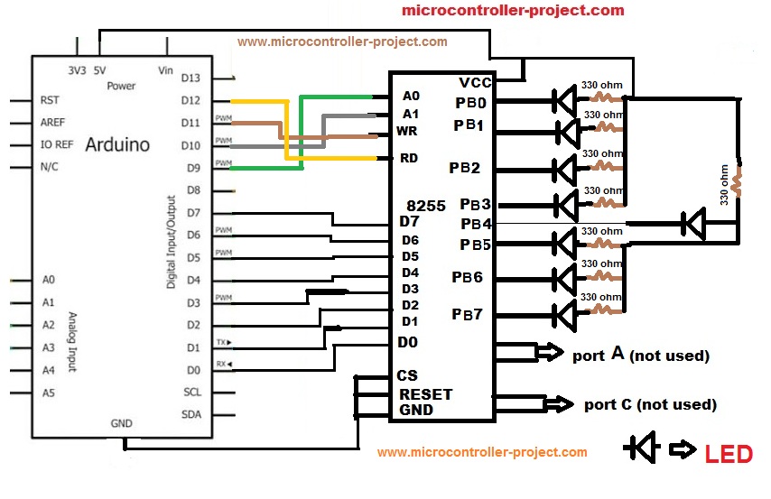
Increasing Digital I/O of Arduino – 8255 interfacing with Arduino – Circuit Diagram
Increasing digital input/output pins of arduino code
Coming to the code portion. First individual pins of arduino are defined to control 8255 chip. Then i defined the individual I/O pins as output in setup() Function. Because i only want to write to Port-B of 8255. In the main function i first disabled read & write. Selected control register of 8255. Loaded control word in control register of 8255. Which set’s all Three Ports of 8255 as output port. Then i enabled write. Enabling write will write my control word in control register of 8255. Then selected Port-B. Made all Pins of Port-B high. After half a second i made Port-B pins low. This continuous High and Low will blink my leds connected to Port-B of 8255 chip.
8255 with Arduino, Increasing Digital I/O of Arduino – Circuit Diagram
Note: You can also use Arduino DDR & PORTD register for pins(0-7). Taking this step will reduce your code statements.
Download the project files .ino, Code(c,HEX) and simulation. Simulation is made in Proteaus 8.0. For simulation execution you first have to install arduino library in Proteaus because proteaus didn’t have pre-installed arduino library to debug Arduino projects. Give us your feed back on the project. In the next Phase i am going to develop standard library for increasing digital I/O of Arduino board Microcontroller with proper Hardware circuit.
Filed Under: Arduino, Microcontroller Projects

Questions related to this article?
👉Ask and discuss on Electro-Tech-Online.com and EDAboard.com forums.
Tell Us What You Think!!
You must be logged in to post a comment.