In the previous tutorial, we learned how to interface an LM35 temperature sensor with Arduino. LM35 is an analog sensor that can be interfaced with Arduino’s analog input pin.
In this tutorial, we’ll cover how to interface a DHT-11 sensor with Arduino. DHT-11 is a digital temperature and humidity sensor. It outputs a much more accurate temperature reading compared to an analog sensor. The output of the DHT-11 is a digital signal that can be read at Arduino’s digital I/O pins.
However, the digital output from the sensor is not in compliance with the common serial data protocols, such as UART, SPI, or I2C. Instead, DHT-11 operates over a one-wire protocol that communicates sensor data digitally.
In this tutorial, we’ll interface the DHT-11 sensor with Arduino, reading sensor data from it, and without the help of an external library. The sensor readings are observed on Arduino’s Serial Monitor, where the serial (UART) communication between Arduino and a desktop computer is set up. Let’s get started.
The DHT-11 sensor
DHT-11 is a basic digital temperature and humidity sensor. The sensor comes pre-calibrated and requires no external circuit for measuring the temperature or humidity.
For sensing humidity, DHT-11 has a resistive component that has two electrodes with a moisture-holding substrate between them. When the substrate absorbs water vapors, it releases ions that increase the conductivity between the electrodes.
When there’s higher relative humidity, the resistance between the electrodes is reduced, and when there’s a lower relative humidity, the resistance between electrodes is increased. This change in resistance is proportional to the relative humidity.

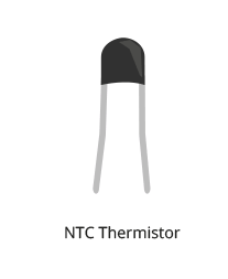
For sensing temperature, the DHT-11 has an NTC Thermistor, which is a thermal resistor. The thermistor contained in the DHT11 has a negative temperature coefficient, so its resistance decreases with increases in temperature.
The sensor contains a 14-pin, 8-bit microcontroller IC that:
- Senses analog signals from the humidity-resistive component and the thermistor
- Converts analog voltages to digital values, according to the stored calibration coefficients
- Outputs a digital signal carrying values of humidity, temperature, and a checksum byte
 The DHT-11 sensor reads te relative humidity value in a percentage range from 20 to 90% RH. It senses temperature in degrees centigrade, ranging from 0˚ to 50˚C.
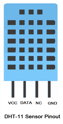
The DHT11 sensor has this pin diagram:
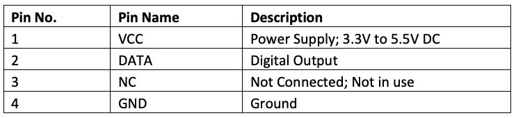
The DHT11 sensor has this pin configuration:
The sensor consumes 0.3 mA when measuring the humidity and temperature and 60 uA in standby mode. It has an accuracy of +/- 1% for the humidity and +/- 1˚ C for the temperature. The sensor can output data at a maximum sampling rate of 1 Hz (i.e. once per second). However, it requires more time between the two readings.
The voltage level of the data output signal depends on the power supply to the DHT11 sensor. If it’s supplied in 5V, then 5V is the level of the digital signal from the sensor for the TON (the time when the digital pulse from the sensor is ON). And, 0V is the level of the digital signal for TOFF (the time when the digital pulse from the sensor is OFF).
With a 5V supply, the DATA pin can have a 20-meter maximum cable to the controller pin. If the sensor is supplied in 3V3, then 3.3V is the level of the digital signal from the sensor for TON, while 0V is the level of the digital signal for TOFF. With the 3V3 supply, the DATA pin can have a one-meter maximum cable to the controller pin.
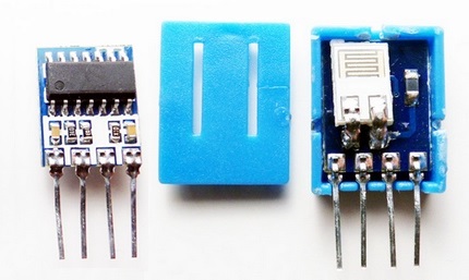
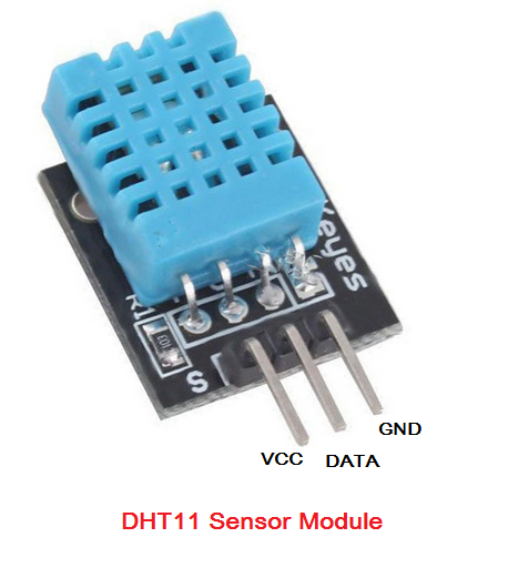
The DHT11 sensor module
A DHT11 sensor module is also available. This module has a built-in supporting circuitry, meaning the sensor can be interfaced without additional circuits. The module has a 10 KΩ pull-up resistor between the VCC and DATA pin, and a decoupling capacitor on the power supply for filtering noise.
The module has only three pins: VCC, DATA, and Ground.
 To support the circuit, the sensor module must ensure proper communication with a controller. If the sensor is used, an external pull-up resistor can be employed. The GPIO of microcontroller boards has built-in, pull-up and pull-down resistors. This ensures the DATA pin of the DHT11 sensor can be directly interfaced with a microcontroller pin that’s configured to use an internal pull-up.
DHT11 vs DHT22
DHT22 is a sensor of the same family. It maintains the same pin configuration, power-supply voltages, and current consumption as the DHT11 sensor. However, DHT22 measures humidity in ranges from 0 to 100% RH, with an accuracy of 2 to 5%. It also measures temperatures ranging from -40˚ to 125˚ C, with an accuracy of +/- 0.5˚ C.
The maximum sampling rate for the DHT22 is 0.5 Hz (i.e. once every two seconds). DHT11 and DHT22 sensors are both used for applications such as environment monitoring, local weather station, and automatic climate control.
Interfacing DHT-11 with Arduino
The DHT-11 sensor can be directly interfaced with Arduino. It can be provided 5V DC and ground from Arduino. The sensor’s data pin can also be directly connected to any of Arduino’s digital I/O pins. But the digital I/O pin to which it’s interfaced must be configured to use an internal pull-up. Otherwise, an external pull-up resistor of 10K must be connected between VCC and DATA pin of DHT-11. Alternatively, the DHT-11 sensor module can be used.
How DHT11 works
The DHT-11 sensor uses a one-wire protocol to communicate the humidity and temperature values. The sensor act as a slave to a host controller.
The digital communication between the DHT11 and the host controller (like Arduino) can be breakdown into four steps:
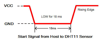
1. Start signal. To start communicating with the DHT11 sensor, the host (Arduino) must send a start signal to the DATA pin of the DHT11 sensor. The DATA pin is then pulled HIGH by the default. The start signal is a logical LOW for 18 milliseconds, which is followed by a LOW-to-HIGH transition (rising edge).
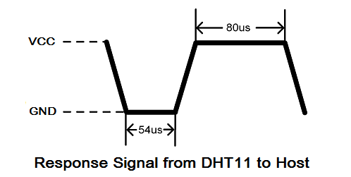
 2. Response. After receiving a start signal from the host, DHT-11 sends a response signal to indicate that it’s ready to transmit the sensor data. The response pulse is a logical LOW for 54 microseconds and then a logical HIGH for 80 microseconds.
3. Data. After sending a response pulse, DHT11 will begin transmitting sensor data containing the values of humidity, temperature, and checksum byte. The data packet consists of 40 bits, with five 8-bit segments or bytes.
The first two bytes contain the value of relative humidity, whereby the first byte is an integral part of the humidity value and the second byte is a decimal part of the humidity value. The next two bytes contain the value of temperature, whereby the third byte is an integral part of the temperature value and the fourth is a decimal part of the temperature value.
The last byte is a checksum byte, which must be equal to the binary sum of the first four bytes. If the checksum byte is not equal to the binary sum of the humidity and temperature values, there’s an error in the values.
The bits are transmitted as timing signals, where the pulse width of the digital signal determines whether it’s bit 1 or bit 0. Bit 0 starts with a logical LOW signal (Ground) for 54 microseconds, followed by a logical HIGH signal (VCC) for 24 microseconds.
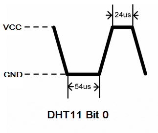
Bit 1 starts with a logical LOW signal (ground) for 54 microseconds, followed by a logical HIGH signal (VCC) for 70 microseconds.

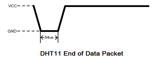
4. End of the frame. After transmitting the 40-bit data packet, the sensor sends a logical LOW for 54 microseconds and then will pull HIGH on the data pin. After this, the sensor goes into a low-power consumption sleep mode. The data from the sensor can be sampled at a rate of 1 Hz or once every second.
Reading sensor data from DHT11
To read sensor data from the DHT11 sensor, Arduino must first send it the start signal. To do so, the pin that DHT11’s DATA pin is interfaced with must be set to a digital output. A digital pulse of 18 milliseconds must be passed to the DATA pin, followed by a rising edge. Immediately afterward, the Arduino pin must be set to a digital input with an internal pull-up.
Now, read the response signal from the DHT11 at the Arduino pin. If a falling edge is detected within 90 microseconds, this means that DHT11 has successfully sent a response pulse.
The data received from the DHT11 sensor can be sampled by polling the logical level of the digital pulse while tracking the pulse width. It’s possible to track the pulse width by measuring the time elapsed from a particular instant of time, while polling for a logical HIGH or LOW.
There are millis() and micros() functions available that track the time elapsed since Arduino boots. The millis() function provides the time from the boot in milliseconds and the micros() function provides the time from the boot in microseconds.
Arduino USART
Arduino has a built-in USART for serial communication with other devices. On Arduino UNO, this USART is available at the digital I/O pins 0 and 1.
This USART is also available on Arduino’s USB port, which is used to program it from Arduino IDE. The same USB port can be used for serial UART communication with a desktop computer or any computing device with a USB interface. To learn more about the UART protocol, check out this UART tutorial for Raspberry Pi.
Arduino Serial Monitor
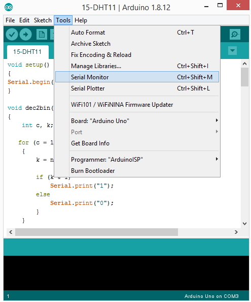
Arduino IDE has an integrated serial monitor that can be used to receive and send serial data via a desktop’s USB ports. The serial monitor can be opened by navigating to Tools->Serial Monitor.
It can also be accessed by clicking the Serial Monitor icon on the top-right corner of the IDE.
![]()
When launching the Serial Monitor, a window opens where the serial data can be sent to the connected serial device. This is also where the received serial data from the device can be viewed. The baud rate and encoding can be set from this window.

Serial communication: Arduino and a desktop computer
In this tutorial, we will send sensor data that’s read from the DHT11 sensor to a desktop computer via Arduino UNO. In this case, the DHT11 will be interfaced with Arduino, and Arduino will be connected to the desktop computer via a USB cable.
The Arduino is programmed so that the sensor data is observed on Arduino IDE’s Serial Monitor.
Arduino Serial Library
To set up serial communication between Arduino and the PC, the Serial Library is useful.
The Serial Library contains these methods:
- Serial.begin() – initializes Arduino for serial communication, and used for setting the baud rate and UART data encoding
- Serial.print() – converts serial data to ASCII characters and sends them over the serial port
- Serial.println() – sends serial data in the form of ASCII characters over the serial port, followed by a carriage return
- Serial.write() – sends binary data to the serial port and returns the number of bytes that are written to the serial port
- Serial.available() – checks if any data is available to read from the serial port
- Serial.read() – reads the data available from the serial port
- Serial.readString() – reads data strings available from the serial port
- Serial.end() – used to close serial communication
Using the external library to read sensor data
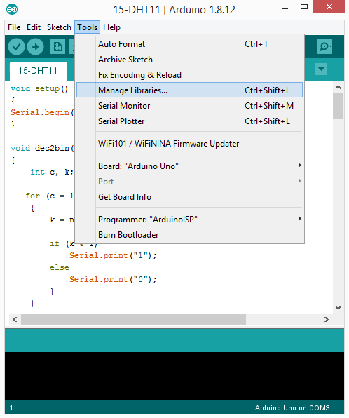
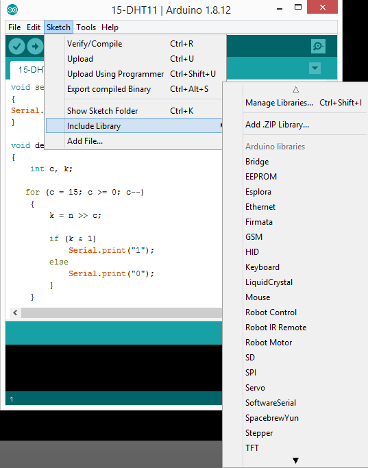
There are many libraries available for the DHT sensors. They can be found by navigating to: Tools-> Manage Libraries.
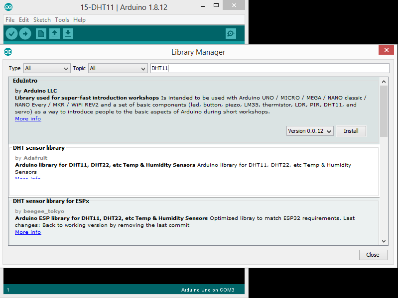
Search one of the libraries for the DHT11 and install its latest version. You can then import this library by navigating to Sketch-> Include Library.
After importing a library, its functions can be used to read sensor data from the DHT11. But what functions? Well, it depends on the library you installed and imported.
Removing a library from Arduino
You may be trying one and then another library for the DHT11 sensor. In fact, there’s a high possibility that many third-party libraries may have the same name. This can cause a problem. So, it’s best to remove an external library if you do not intend to use it. An external library can have a name conflict or function name conflict with any library that you might import in the future.
To remove an external library, you’ll first need to find its folder.
- On macOS and Linux, external libraries are stored in Documents/Arduino/libraries/<library-name(s)>
- On Windows, external libraries are stored in My Documents/Arduino/libraries/<library-name(s)>
To remove a library, delete its folder from the libraries folder and restart Arduino IDE. Now, the deleted library will be gone from the Sketch-> Include Library. After deleting an external library, you can no longer import it or compile an Arduino sketch using that library. If you intend to use that library again, you can backup it up as an archive file.
Reading sensor data from DHT-11 (without the library)
It’s possible to write our own functions to read sensor data from the DHT11.
The following functions can be sued to write our own DHT11 functions or library:
- pinMode() function – to set a pin as digital input or output
- digitalWrite() function – to write digital signal at a pin
- digitalRead() function – to read digital signal at a pin
- delay() function – to provide a delay in milliseconds
- delayMicroseconds() function – to provide a delay in microseconds
- millis() function – to measure time lapse in milliseconds
- micros() function – to measure time lapse in microseconds
Check out the Arduino recipe below. It uses the above-mentioned functions in Arduino sketch to write functions that can read the DHT11 sensor data.
Recipe: Reading sensor data from DHT-11 without using an external library
In this recipe, we write our own functions to read sensor data from the DHT11 on Arduino. The functions are written to pass sensor data to the serial port.
Components required
1. Arduino UNO x1
2. DHT11 sensor x1
3. USB cable for Arduino x1
4. Desktop computer x1
5. Male-to-male jumper wires or connecting wires
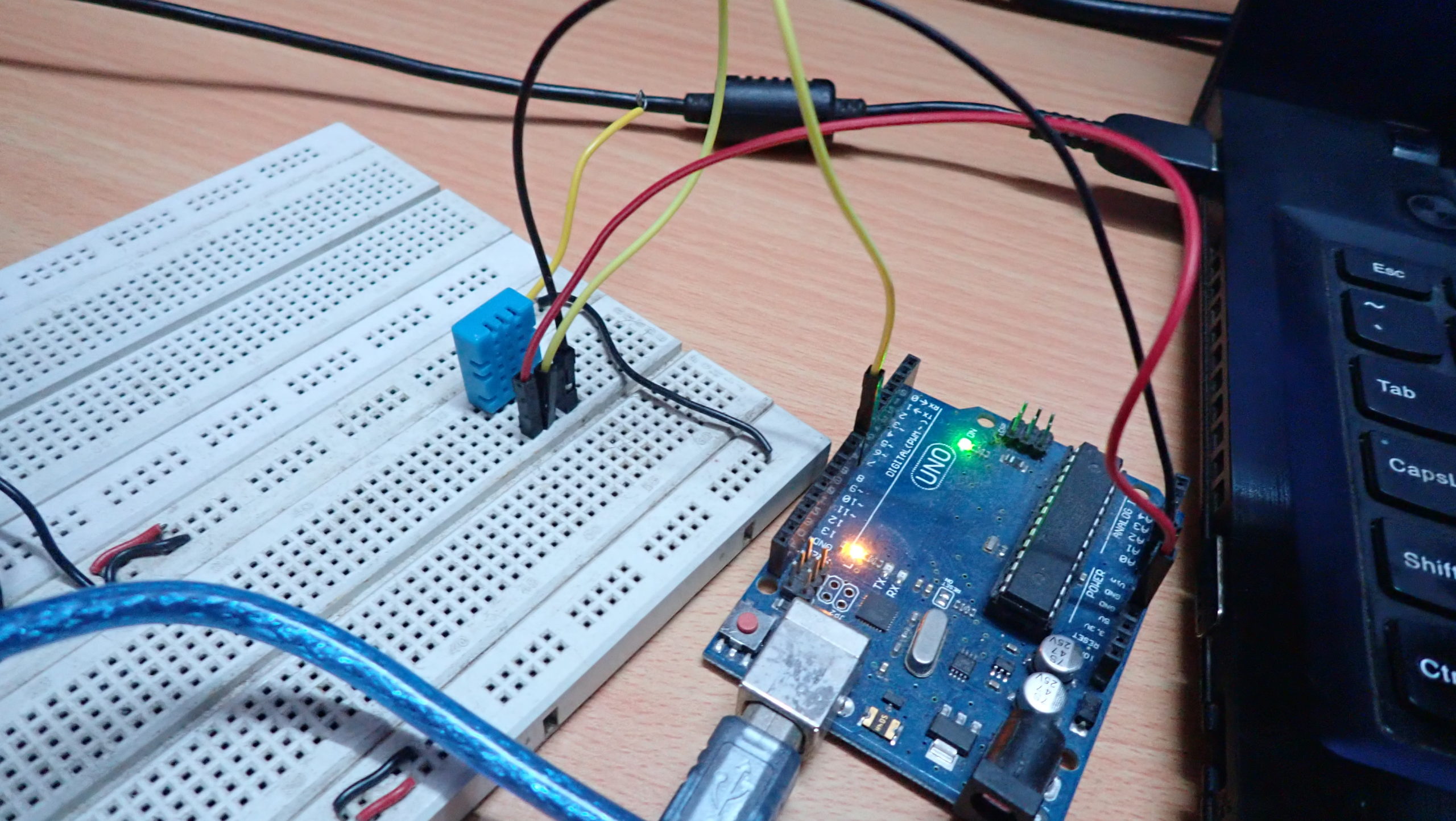
Circuit connections
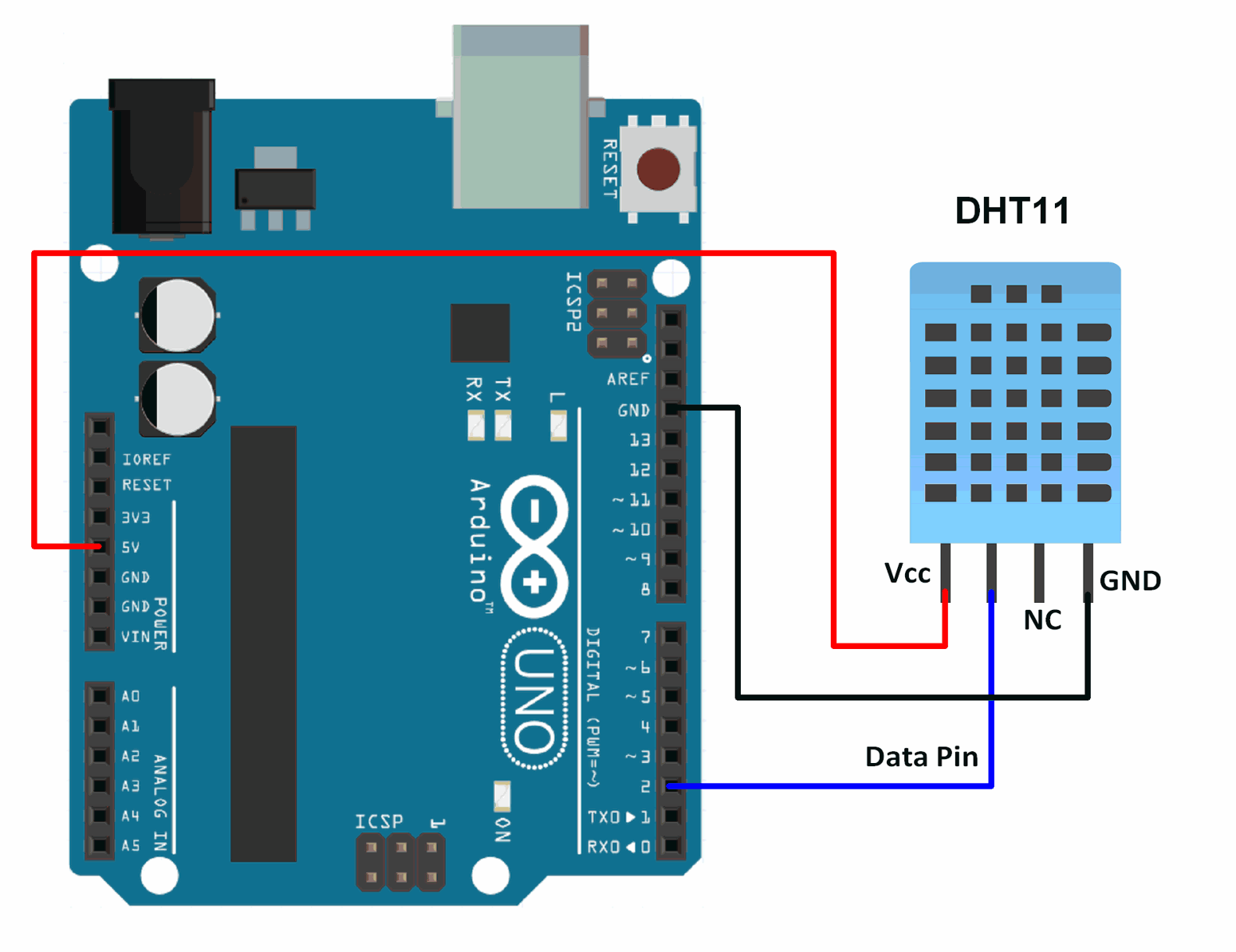
- Connect Arduino with the PC via a USB cable
- Provide ground and VCC to the DHT11 sensor from Arduino’s ground and 5V pin, respectively
- Connect the data pin of the DHT11 sensor with pin 2 of Arduino UNO
Arduino sketch
How the project works
The data pin of DHT11 is connected to Arduino UNO’s pin 2. Arduino is programmed to send a start signal to the DHT11 sensor, and then to read the response pulse and serial data from the sensor.
For detecting the response signal and reading serial data from DHT11, the input digit signal at the Arduino pin is polled and the pulse width for the TON and TOFF is determined. This is done by comparing the time elapsed for a logical HIGH input after the rising edge of the signal and the time elapsed for a logical LOW input after the falling edge of the signal at the Arduino pin.
By measuring the pulse width of the TON signal of the response signal, it determines if the start pulse has been successfully applied to DHT11’s data pin. If the pulse width of the TON after the rising edge in response signal does not exceed 90 microseconds, this means the start signal has been successfully applied to DHT11’s DATA pin. Otherwise, there will be a TIMEOUT_ERROR when applying the start signal to DHT11’s data pin.
After receiving the response pulse from DHT11, the serial data from it is read at the Arduino pin. Bits 0 and 1 are detected by measuring the pulse width after the rising edge of the signal. If the pulse width exceeds 30 microseconds, it’s bit 1. Otherwise, it’s bit 0.
The bits are stored in a 16-bit variable and transferred to other 16-bit variables for the humidity and temperature values, and to an 8-bit variable for checksum byte.
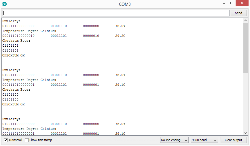
The read bits — with the humidity and temperature value, checksum byte, and error codes — are sent to the serial port in this format.
If there’s timeout error in applying the start signal, send this to the serial port:
Humidity:
<bit0-bit15 from DHT11> \t <bits representing integral part humidity> \t <bits representing decimal part of humidity> \t <humidity value>
Temperature Degree Celsius:
<bit16-bit31 from DHT11> \t <bits representing integral part temperature> \t <bits representing decimal part of temperature> \t <temperature value>
Checksum Byte:
<bit32-39 from DHT11>
<Binary Sum of humidity and temperature values>
CHECKSUM_OK {if bit32-39 is same as binary sum of humidity & temperature value}/CHECKSUM_ERROR { if bit32-39 and binary sum of humidity & temperature value are not same}
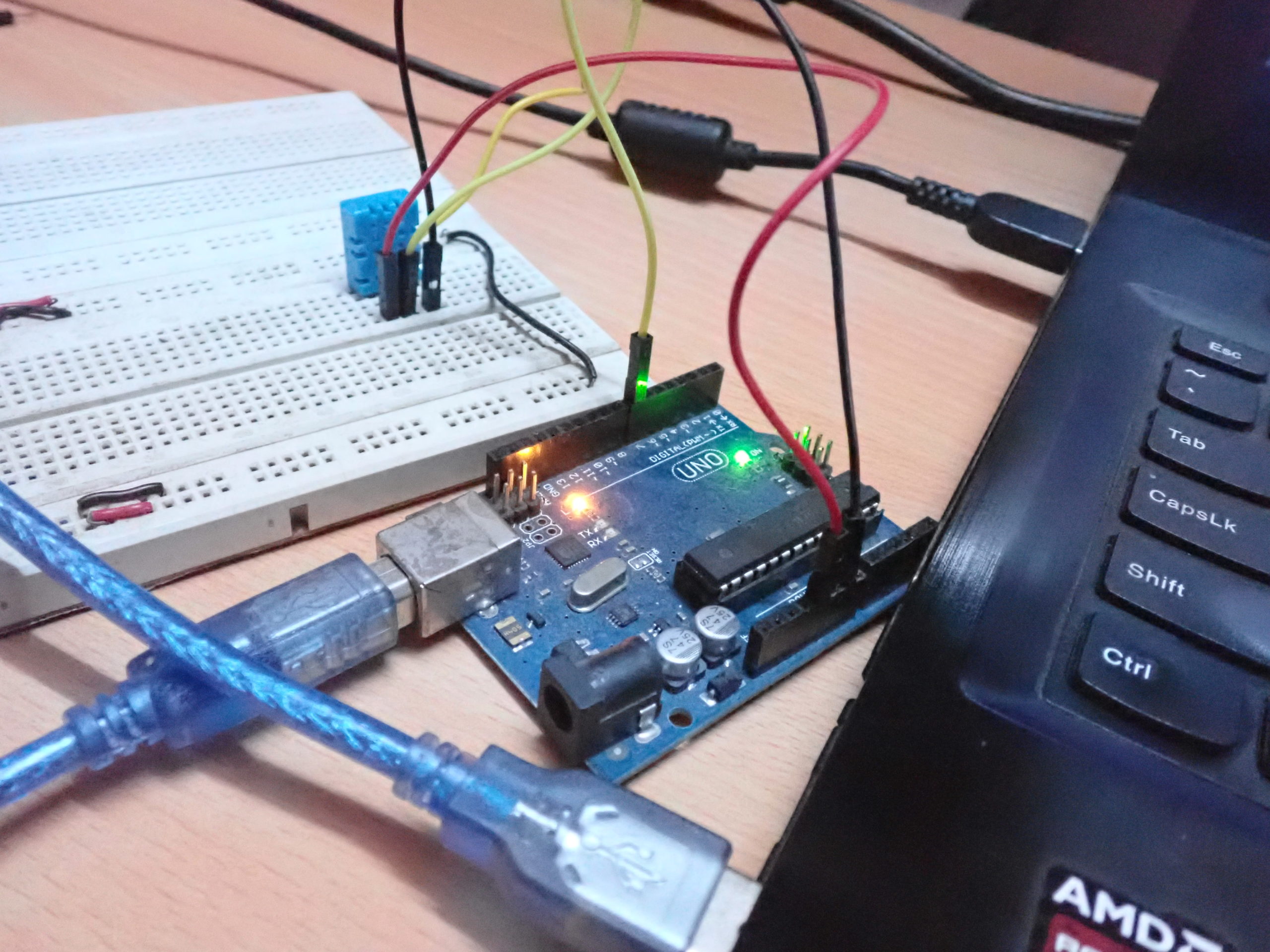
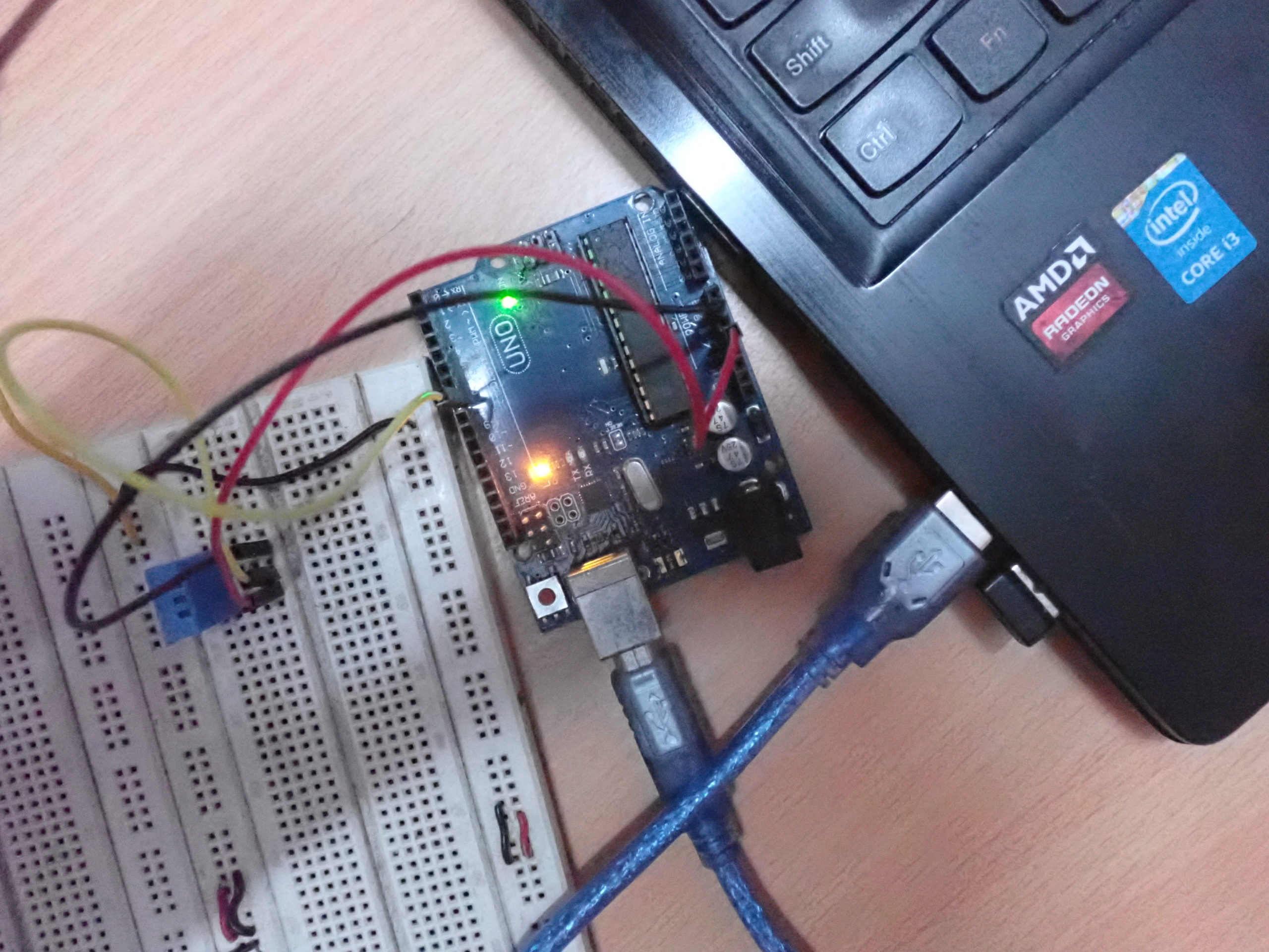
Results
 Programming guide
The Arduino sketch begins with the setup() function, where the baud rate for the serial communication is set to 9600 bps.
Then, the following user-defined functions are written:
dec2bin(int n) – converts a 16-bit integer to its binary representation. It loops through a 16-bit integer value bit-by-bit right, shifting one bit each time and masking it with 1 (using & operator) to determine if that particular bit in the integer value is 1 or 0. This function returns nothing, but serially prints the binary representation of the argument passed to it. It’s used to convert the read humidity and temperature values to their binary representations.
dec2bin8(int n) – converts an 8-bit integer to its binary representation. It loops through the 8-bit integer value bit-by-bit right, shifting one bit each time and masking it with 1 (using & operator) to determine if that particular bit in the integer value is 1 or 0. The function returns nothing, but serially prints the binary representation of the argument passed to it. It’s used to convert the read checksum value, the integral and decimal parts of humidity value, and the integral and decimal parts of temperature value to their binary representations.
wait_for_dht11() – provides a delay of two seconds. This time is required to get DHT11 ready for data transmission after its host (Arduino) boots. If this delay is not provided, the DHT11 sensor will not respond to the host controller and, in initial attempts to read the sensor data from DHT11, there will be a timeout error.
void wait_for_dht11()
{
delay(2000);
}
start_signal(uint8_t dht11_pin) – generates the start signal for the DHT11 sensor. This function takes the pin where DHT11’s DATA pin is interfaced as an argument. The pin is first set as digital output using the pinMode() function. It’s cleared (LOW) for 18 milliseconds using the digitalWrite() and the delay() functions. Then, it’s set (HIGH) to provide the rising edge of the digital signal. Immediately afterward, the pin is set as digital input and it’s pulled HIGH.
void start_signal(uint8_t dht11_pin)
{
pinMode(dht11_pin, OUTPUT);
digitalWrite(dht11_pin, LOW);
delay(18);
digitalWrite(dht11_pin, HIGH);
pinMode(dht11_pin, INPUT);
digitalWrite(dht11_pin, HIGH);
}
read_dht11(uint8_t dht11_pin) – used to read sensor data from DHT11. It takes the pin where DHT11’s DATA pin is connected as an argument. First, the variables are defined to store the:
- Raw humidity value (containing both integral and decimal parts)
- Raw temperature value (containing both integral and decimal parts)
- Checksum byte
- Bit stream from the DHT11 sensor (variable ‘data’)
- Integral part of the humidity value
- Decimal part of the humidity value
- Integral part of the temperature value
- Decimal part of the temperature value
- Variable to store instant of time at the rising or falling edge of the signal
void read_dht11(uint8_t dht11_pin)
{
uint16_t rawHumidity = 0;
uint16_t rawTemperature = 0;
uint8_t checkSum = 0;
uint16_t data = 0;
uint8_t humi;
uint8_t humd;
uint8_t tempi;
uint8_t tempd;
unsigned long startTime;
A for-loop is run to detect DHT11’s response signal and bit stream. A variable ‘live’ is declared to store the TON time and the current instant of time is stored in the variable ‘startTime.’
for ( int8_t i = -3 ; i < 80; i++ ) {
byte live;
startTime = micros();
In a do-while loop, the response signal will be detected. It’s determined if the digital signal at Arduino pin is HIGH as a condition for the loop. While the signal remains HIGH, the elapsed time from the last measured time instant is polled.
If it’s greater than 90 microseconds, the start signal was not properly applied to the DHT11 DATA pin. Otherwise, if there is a falling edge causing the while loop to exit before 90 microseconds, the response signal has been successfully received from DHT11.
Now, we are ready to detect the bit stream from DHT11.
do {
live = (unsigned long)(micros() – startTime);
if ( live > 90 ) {
Serial.println(“ERROR_TIMEOUT”);
return;
}
}
while ( digitalRead(dht11_pin) == (i & 1) ? HIGH : LOW );
The for-loop has already run four times in an attempt to detect the response signal. The Arduino pin is read LOW after exiting the previous do-while loop due to a falling edge. Now we can start reading the bit stream. When the loop counter is greater or equal to 0 and is even (like 0, 2, 4, 6, 8, etc.) when it is masked with 1 (& operation), the following if the condition will be false. So, do nothing when there is the TOFF of the digital pulse.
if ( i >= 0 && (i & 1) ) {
When the loop counter is odd, the if condition will be true. Check if the time elapsed (for the TON of the digital pulse) is greater than 30 microseconds. If so, left shift the variable storing the bit stream and append 1. Otherwise, simply left shift the variable storing bit 0.
data <<= 1;
// TON of bit 0 is maximum 30 usecs and of bit 1 is at least 68 usecs.
if ( live > 30 ) {
data |= 1; // we got a one
}
}
When the loop counter has run 31 times since detecting the bit stream, which means 16 bits have been read, store that bit stream to the raw humidity value. When the loop counter has run 63 times since detecting bit stream, so the next 16 bits have been read, store that bit stream to the raw temperature value.
When the loop counter has run 79 times since detecting a bit stream, and 8 bits have been read, store that bit stream to checksum byte.
switch ( i ) {
case 31:
rawHumidity = data;
break;
case 63:
rawTemperature = data;
case 79:
checkSum = data;
data = 0;
break;
}
}
Now that we have the humidity value, temperature value, and checksum byte, transfer them to the serial port in the format stated above.
Serial.println(“Humidity: “);
dec2bin(rawHumidity);
Serial.print(“\t”);
humi = rawHumidity >> 8;
dec2bin8(humi);
Serial.print(“\t”);
rawHumidity = rawHumidity << 8;
humd = rawHumidity >> 8;
dec2bin8(humd);
Serial.print(“\t”);
Serial.print(humi);
Serial.print(“.”);
Serial.print(humd);
Serial.print(“%”);
Serial.println(“”);
Serial.println(“Temperature Degree Celcius: “);
dec2bin(rawTemperature);
Serial.print(“\t”);
tempi = rawTemperature >> 8;
dec2bin8(tempi);
Serial.print(“\t”);
rawTemperature = rawTemperature << 8;
tempd = rawTemperature >> 8;
//tempd = (byte)rawTemperature;
dec2bin8(tempd);
Serial.print(“\t”);
Serial.print(tempi);
Serial.print(“.”);
Serial.print(tempd);
Serial.print(“C”);
Serial.println(“”);
Serial.println(“Checksum Byte: “);
dec2bin8(checkSum);
Serial.println(“”);
dec2bin8(tempi + tempd + humi + humd);
Serial.println(“”);
if((byte)checkSum == (byte)(tempi + tempd + humi + humd)){Serial.print(“CHECKSUM_OK”);}
else {Serial.print(“CHECKSUM_ERROR”);}
Serial.println(“”);
Serial.println(“”);
Serial.println(“”);
}
In the loop() function, the wait_for_dht11(), start_signal() and read_dht11() functions are executed five times in the same sequence. So, the sensor data is read five times from the DHT11 sensor. The serial communication is then closed using the Serial.end() method.
Note: the above code will work only with the DHT11 sensor. It will not work with other sensors in the DHT family.
In the next tutorial, we’ll cover serial (USART) communication using Arduino.
Filed Under: Arduino

Questions related to this article?
👉Ask and discuss on EDAboard.com and Electro-Tech-Online.com forums.
Tell Us What You Think!!
You must be logged in to post a comment.