In previous tutorials, we’ve covered serial communication using the UART and software serial in Arduino. The universal asynchronous receiver/transmitter (UART), I2C, and SPI are the most commonly used serial interfaces in embedded systems.
UART is useful for full-duplex serial communication with a single device over two wires. The I2C or two-wire interface (TWI) is used for half-duplex synchronous serial communication with multiple devices in a master-slave fashion. SPI bus is used for full-duplex synchronous serial communication with multiple devices.
Now, in this tutorial, we’ll learn about synchronous serial communication in Arduino using the inter-integrated circuit (I2C) bus.
The I2C bus
The I2C, or TWI, is a synchronous master-slave serial communication protocol originally developed by Philips Semiconductors (which is now NXP). The I2C bus has only two wires: one is a data line (SDA) and one is a clock line (SCL).
On a two-wire bus, hundreds of master and slave devices can communicate serial data using the I2C protocol.
The I2C is a master-slave type bus and there should be at least one master device to control the two-wire bus.
The master device is responsible for synchronizing data transfers by:
- Generating the clock signal
- Selecting a slave device for communication
- Controlling the read/write operations over the bus
Since there is just one data line, only the half-duplex communication with a single slave device is possible at one time. This means any number of master devices can be connected to the I2C bus, but only one master can control the bus at one time.
The wires are pulled HIGH by default, using the pull-up resistors and the I2C drivers are open-drain (meaning, they can only pull the line LOW). This successfully avoids any bus contention.
Each I2C slave that’s connected to a bus must have a unique address. The master device uses in-band addressing to access the communication with the slave devices. The I2C addresses of the various slave devices are decided by NXP.
Many slave devices have a configurable I2C address. The in-band addressing can be a 7 or 10-bit. In 7-bit addressing, 112 slave devices can be connected to the bus. In 10-bit addressing, 1008 slave devices can be connected to the bus. Also, the I2C master can use both the 7 and 10-bit addresses on the same bus.
Additionally, there are some breakout boards that allow communication with multiple slave devices using a common address. In these boards, the slave devices are multiplexed using an on-board controller.
The implementation of the I2C protocol simply requires two open-drain channels on a device. In most of the controllers/computers, there’s dedicated hardware to manage the I2C protocol.
The data transfer rate over the I2C depends on the clock frequency generated by the I2C master.
There are standard I2C clock speeds, which include:
- 100 to 400 kHz (standard I2C)
- 1 MHz (fast-mode I2C)
- 3.4 MHz (high-speed I2C)
- 5 MHz (ultra fast-mode I2C).
Typically, the I2C bus uses 5V or 3V3 TTL logic levels. It’s recommended to connect the voltage-compatible devices together over the I2C bus, otherwise, the low-voltage device is at risk of damaging its I2C channels when receiving data. If two devices have different TTL voltage levels, a suitable voltage-shifter must be used between the devices and connected through the two-wire bus.
The I2C protocol
Data communication is always initiated by a master device on the TWI bus. A master device generates a start condition for accessing the bus. When generating the start condition, it’s decided which master accesses the bus if two or more are trying to do so at the same time.
After successfully doing so, the master transmits an in-band address in the form of an address frame to select a slave device for communication. The master has to read data from or write data to the selected slave device, which is indicated in the address frame.
After selecting a slave device, the master can read or write data in the form of 8-bit data packets. After exchanging each data packet, the receiving device sends an acknowledgment bit to the sender to indicate that the byte has been successfully communicated.
Once gaining access to the I2C bus, a master can generate multiple start conditions to talk with a slave device several times — or to talk with many slave devices, one after the other.
To release the bus for other masters, however, the master needs to generate a stop condition. The slave devices can never initiate communication on their own or control the bus, but they can temporarily hold the clock pulse (after a stop condition) to make the masters wait to access the bus. This is called clock stretching. (Learn about the I2C protocol in more detail here).
Applications of the I2C bus
Since multiple devices can communicate data on just two wires using the I2C protocol, the I2C/TWI interface is broadly used by sensors and embedded modules. Some examples of sensors that use the I2C bus for communicating data are ADXL345 accelerometer, L3G4200D gyroscope, MC5883L magnetometer, BMP180 pressure sensor, DS1307 RTC, and there are others.
Using I2C in Arduino boards
Most Arduino boards have at least one I2C module. The I2C module may be accessible through one or more ports on the board.
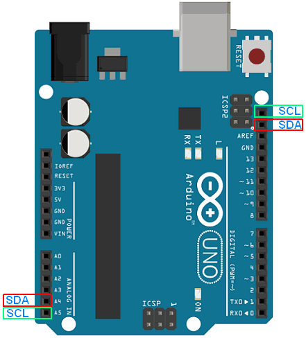
The I2C pins are not internally pulled up, so they may need to be pulled HIGH using external resistors depending upon the I2C device they are connected to.
The I2C pins on an Arduino UNO are shown here:
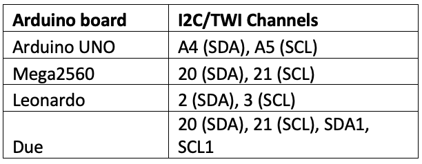
This table summarizes the I2C pin location on various Arduino boards…
The wire library
It’s easier to talk with I2C/TWI devices using Arduino partly because this platform provides a library: A wire to manage communication of Arduino boards on an I2C bus.
Arduino boards can be configured as an I2C master and as an I2C slave. The wire library uses a 32-byte buffer, so any I2C data transfer should be within this limit. If more bytes are communicated in a transmission, the exceeding bytes will be left out.
The wire library can be imported in an Arduino sketch using this statement:
#include <Wire.h>
The wire library has these methods:
wire.begin() – used to join the I2C bus as a master or slave. It has this syntax:
Wire.begin()
or
Wire.begin(address)
If Arduino joins the I2C bus as a master, the method must be called without arguments. If Arduino joins the I2C bus as a slave, then an arbitrary 7-bit address must be passed as the argument. As a slave, it can have an address between 8 and 127. The addresses 0 to 7 are reserved, however, and not used by Arduino.
Here are valid examples of this method:
Wire.begin() //Arduino as I2C master
Wire.begin(8) // Arduino as I2C slave
Wire.setClock() – used by Arduino and configured as an I2C master. This method is used to change the clock frequency for the I2C bus. The I2C slaves have no minimum frequency, although 100 kHz is the baseline. This method has this syntax:
Wire.setClock(clockFrequency)
It takes the clock frequency in Hertz as an argument. Here’s a valid example:
Wire.setClock(3200)
Wire.beginTransmission (address) – used by Arduino and configured as an I2C master. This method is used to begin transmission to an I2C slave. The address of the selected I2C slave is passed as an argument in the function. It has this syntax:
Wire.beginTransmission(address)
And here’s a valid example:
Wire.beginTransmission(8)
Wire.write() – used to write data on the I2C bus. It can be used by Arduino as both an I2C master and an I2C slave. As a master, this method must be used between calls to the beginTransmission() and endTransmission() methods.
As a slave, this method can be used in response to a request from a master device. It can be used to transmit a value, a string, or an array of bytes. It has this syntax:
Wire.write(value)
or
Wire.write(string)
or
Wire.write(data, length)
Here are valid examples:
Wire.write(7)
Wire.write(“Hello”)
Wire.write(arraybytes, 5) //arraybytes is an array of 5 byte values
array of 5 byte values
Wire.onReceive(handler) – used by Arduino and configured as a slave. It assigns a handler function to be called in response to when data is received from the I2C master. The user-defined handler function must take the number of bytes read from the master as an argument if needed. The function must also be of the void type and return nothing. It has this syntax:
Wire.onReceive(handler)
Here’s a valid example:
Wire.onReceive(receiveEvent);
void receiveEvent()
{
Serial.print(“data received from I2C master);
}
Wire.requestFrom() – used by Arduino and configured as I2C master. This method is used to request data from the I2C slave. The requested data is then retrieved by the master Arduino using the Wire.available() and Wire.read() methods. It has this syntax:
Wire.requestFrom(address, quantity)
Wire.requestFrom(address, quantity, stop)
The method takes two arguments — the I2C address of the slave device and the number of bytes requested. It has an optional Boolean argument – stop that can either be ‘True’ or ‘False.’
The stop is by default True. When it’s True, a stop condition is generated after the request, releasing the bus. When it’s False, a restart condition is generated after the request, allowing the Arduino master to continue using the bus. The method returns the number of bytes received from the slave device. Here’s a valid example:
Wire.requestFrom(8, 6, true)
Wire.onRequest(handler) – used by Arduino configured as a slave. It assigns a handler function to be called in response when the I2C master requests data from this slave. The user-defined handler function takes no arguments and returns nothing. This method has this syntax:
Wire.onRequest(handler)
And here’s a valid example:
Wire.onRequest(requestEvent);
void requestEvent()
{
Wire.write(“Master, get this data”);
}
Wire.available() – used as Arduino is configured as a master or slave. It returns the number of bytes available for retrieval from the I2C bus. It must be called by the Arduino master after a call to requestFrom() and by the Arduino slave inside the onReceive() handler. It has this syntax:
Wire.available()
The method takes no arguments. This is a valid example:
while (Wire.available())
{
char c = Wire.read();
}
Wire.read() – reads a byte transmitted from a slave device to a master after a call to requestFrom() or if transmitted from a master to a slave. It has this syntax:
Wire.read()
The method takes no arguments. This is a valid example:
Wire.requestFrom(2, 6);
while(Wire.available())
{
char c = Wire.read();
}
Wire.endTransmission() – used by an Arduino and configured as I2C master. This method is used to end transmission to the I2C slave and transmit bytes queued using the write() method. Therefore, it must be called after a call to write() method. It has this syntax:
Wire.endTransmission()
Wire.endTransmission(stop)
The method takes an optional argument – stop. It’s a Boolean value, which is set to True generates a stop condition, releasing the bus. If set to False, it generates a restart condition, allowing the Arduino master to continue to access the bus.
This method returns a status byte, which can be 0, 1, 2, 3, or 4.
- If the status byte is 0, then the transmission has ended successfully.
- If it’s 1, the data was too long to fit the 32-byte buffer
- If it’s 2, NACK was received on the transmitting address
- If it’s 3, NACK was received on the transmitting data
- If it’s 4, an error occurred.
Here’s a valid example of this method:
Wire.beginTransmission(8);
Wire.write(“Hello, I am I2C Master”);
Wire.endTransmission();
Arduino as the I2C master
Arduino can be configured as an I2C master by calling the Wire.begin() without any arguments. The master Arduino can set the I2C clock frequency using the Wire.setClock() method if the clock speed needs to be modified.
It can transmit data to a slave by calling the Wire.beginTransmission(), Wire.write(), and Wire.endTransmission() methods. It can also request data from a slave using the requestFrom() method and retrieve the requested data using the Wire.available() and Wire.read() methods.
Arduino as the I2C slave
Arduino can join the I2C bus as a slave by calling the Wire.begin() method with its address passed as an argument. It can execute a block of code in response to data received from the master using the Wire.onReceive(handler) method.
In the handler function, the received bytes can be read using the Wire.available() and Wire.read() methods. It can also execute a block of code in response to a request from the I2C master using the Wire.onRequest(handler) method.
In the handler function, requested data can be sent using the Wire.write() method.
In the next tutorial, we’ll cover how to interface an ADXL345 accelerometer sensor with Arduino using the I2C interface.
You may also like:


Filed Under: Arduino, Tutorials

Questions related to this article?
👉Ask and discuss on Electro-Tech-Online.com and EDAboard.com forums.
Tell Us What You Think!!
You must be logged in to post a comment.