In the previous tutorial, we learned how to display custom characters on a character LCD. Character LCD is the most commonly used display device in embedded systems and circuits.
Although character LCDs are from sophisticated, they provide a simple interface that’s easy to use and learn. They also convey useful information about operating conditions, warnings, and basic text-based interface for interaction with the device user.
Most of the embedded devices involve sensors and/or actuators. LCDs in these devices are used to display sensor data or the status of an action.
We have already discussed interfacing analog sensors with Arduino. In this tutorial, we’ll learn how to interface an LM35 temperature sensor when using Arduino.
LM35 is a general-purpose temperature sensor from Texas Instruments. It can be used to sense ambient and surface temperatures. The sensor is calibrated to centigrade scaling and its output is directly proportional to the centigrade temperature.
We’ll design a basic centigrade-temperature sensor using LM35 and display real-time room temperature on a character LCD.
LM35 temperature sensor
LM35 is an analog, general-purpose temperature sensor. Its sensor gain is linear so that the temperature value can be obtained by a simple two-variable equation. Both LM35 and LM35A can measure temperature ranging from -55˚ to 150˚C, with an accuracy of +/-0.25˚C at room temperature and +/-0.75˚C at full scale.
LM35C and LM35CA of the same family have a temperature range of -40˚ to 110˚C while LM35D has temperature range of 0˚ to 100˚C. The sensor outputs a voltage that gains 10mV per degree Celsius.
Regardless of the packaging, the LM35 sensor has three pins for interfacing in a circuit. Two of these pins are used for the power supply and one is used for the output. The sensor requires a single power supply or a plus-minus power supply between 4 to 30V.
The sensor only draws 60 uA from the supply and has low self-heating (of 0.08˚C). The output of the sensor should be applied to an ADC or analog input of a controller to obtain a digital reading. The sensor can be interfaced to obtain a basic centigrade reading (of 2˚ to 150˚C) or a full-scale reading (of -55˚ to 150˚C).
LM35 sensor packaging
The LM35-series sensors come packaged in hermetic-to-transistor packages. LM35C, LM35CA, LM35D are typically available in a plastic TO-92 package. The LM35D is also available in an 8-lead, surface-mount package and a plastic TO-220 package.
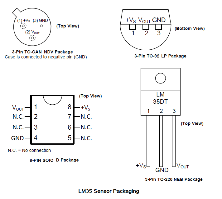
The pin configuration of the LM35 sensor depends on its packaging. As is clear from the above image, different packaging offers a different pinout.
In this tutorial, the LM35 sensor in the TO-92 package is used. In this package, LM35 sensor is a three-terminal device. From the front view (where the label is visible), the far-left terminal is a positive supply pin (Vs). The middle one indicates voltage output from the LM35 (Vout) and the far-right terminal is a sensor ground (GND).
 LM35 sensor characteristics
The LM35 series includes these sensors: LM35, LM35A, LM35CA, LM35C, and LM35D.
With a supply of 5V DC and a load of 50 uA, the LM35A and LM35CA sensors typically offer:
- An accuracy of +/-0.2˚ to +/-0.4˚C
- A non-linearity of 0.18˚C above the operating temperature range
- A sensor gain of 10mV/˚C
The quiescent current, change in quiescent current, and temperature coefficient of the quiescent current are in the micro-ampere range.
With a supply of 5V DC and a load of 50 uA, the LM35, LM35C, and LM35D sensors typically have:
- An accuracy of +/-0.4˚ to +/-0.8˚C
- A non-linearity of 0.3˚ C above the operating temperature range
- A sensor gain of 10mV/˚C.
The quiescent current, change in quiescent current,t and temperature coefficient of the quiescent current are also in micro-ampere range.
Therefore, LM35 sensors can be relied on to obtain a precise and an accurate temperature over a wide operating range. These sensors can be used to read ambient and surface temperatures.
However, the sensors require a minimum voltage to operate, depending on the temperature. This graph shows the minimum operating voltage in regards to the temperature.
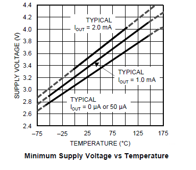
Based on the above graph, it’s possible to conclude that if the sensor is supplied at least 3.3 to 5V, it can sufficiently operate in the normal temperature range.
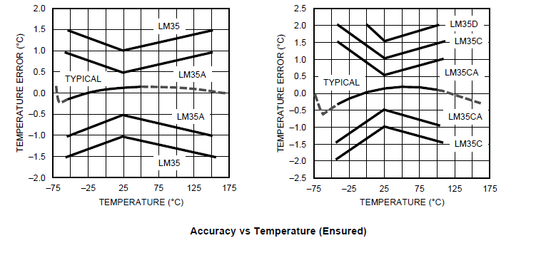
The below graphs show temperature errors of different variants against the operating temperature range.
If we consider the start-up response, the sensor is capable of a stable voltage output in 40 uSEC. So, the minimum time required to sample voltage from the sensor should be at least 40 uSEC.

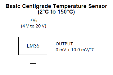
Centigrade sensor with LM35
LM35 is designed to serve as a centigrade temperature sensor. It can be interfaced to read temperature in either a positive or full range.
For the basic centigrade temperature sensor, LM35 is interfaced as shown in this circuit diagram.
For operating in full range, LM35 is interfaced as shown in this circuit diagram.

In either case, the sensor gains 10 mV/˚C. In the full-scale configuration, the sensor gain is obtained in reverse polarity of the negative temperatures.
The temperature can be derived from the voltage output of the sensor according to this equation:
Temperature (in ˚C) = LM35 Output Voltage (in Milli-Volt)/10
Interfacing LM35 with Arduino
The LM35 sensor can be directly interfaced to the analog input pin of Arduino. As Arduino can only sense unipolar voltages, LM35 can be interfaced with Arduino for only basic centigrade temperature sensing.
For full-scale temperature sensing, LM35 must be interfaced through a bipolar-to-unipolar converter. The sensor outputs up to 1.5V for a maximum temperature (150˚C) and at least 20 mV for a minimum temperature (2˚C) in the case of basic interfacing.
The analog input pins on Arduino boards can conveniently read voltages from 0 to 3.3V or 5V. So, for basic centigrade temperature sensing, Arduino can read signals from the LM35 sensor for its complete range of operations.
The sensor draws current in the micro-Ampere range. The output pin of the LM35 sensor should be directly interfaced to any of Arudino’s analog input. However, single-power supply to the sensor can be sourced directly from the Arduino.
Ideally, it’s recommended to supply power to the LM35 from the 5V power output of Arduino so that this sensor can operate at its maximum temperature.
Arduino requires 2.5 clock cycles to sample voltage at the analog input pins. This takes a maximum of 20 micro-seconds while the voltage output from the LM35 stabilizes in about four micro-seconds. So, if the sensor is supplied constant DC power, getting a stable reading from the LM35 sensor is simple.
However, if Arduino sources power to the LM35, the power output is inherently unstable. Fluctuations in power to the LM35 sensor can result into slight variations in the sensor readings. Other operating factors can also lead to fluctuations in the LM35 output. So, it’s recommended to take several voltage samples from the sensor (and take the mean of those samples) as the final result before displaying or passing the sensor reading.
LM35 sensor testing
Before using the LM35 sensor with a controller, it’s important to know if the sensor is working properly. This sensor can be easily tested with a multimeter.
Its maximum output ranges from -1 to 6V, according to its datasheet. But its output should never exceed 1.5V as this is the output of its maximum operating temperature.
A single power supply from any source can supply the LM35 and its output voltage can be checked from a multimeter. If it’s within an acceptable range (i.e. less than 1.5V), this means the sensor is working properly. For a normal temperature (25˚C), the output of the sensor should be about 250 mV.
Choosing an analog reference
An important factor in obtaining data from the LM35 sensore is the voltage reference at the analog input pin. The default analog reference is 5V/3.3V, depending on the Arduino board. But the voltage output of Arduino is also un stable, which can lead to fluctuations or errors in the interpretation of the sensor signals.
One solution to this problem is to set an internal voltage reference for Arduino. This defaults to 1.1V of an internal voltage reference at the analog input, which is quite stable compared to the 5V/3.3V power output of Arduino — or any external voltage reference that’s applied to the Arduino board.
The ideal way to derive a reliable reading from the sensor, however, is to take multiple samples over a period of time and obtain the mean of those samples.
Sampling the data
Arduino can sample analog voltage from a sensor at a rate of up to 15k SPS (samples per second). It requires at most 20 micro-seconds for sampling from a source. The complete analog-to-digital conversion takes 65 to 260 micro-seconds. The output of LM35 sensor will stabilize in about four micro-second (as per its start-up response).
With an uninterrupted DC supply to the sensor, Arduino can reliably sample voltage output from the LM35. Data from the LM35 can be logged at intervals of a few hundred micro-seconds, given a sampling rate at Arduino’s analog input pins.
Although Arduino confidently samples voltage from the LM35 sensor, it’s also important to be aware of how it might be manipulated in the user program.
For example, there can be significant variation in the voltage output of LM35 due to factors such as:
- An unstable power source to the sensor
- The selection of analog reference at Arduino’s analog input
- Unreliable connections (such as on the breadboard)
- Other operating conditions of the circuit
To overcome such issues, we decided to take large number of voltage samples from the LM35 sensor and take the mean of those values to derive a reliable temperature reading.
We started with 100 voltage samples over a delay of one second and noticed that there was a large variation in the derived temperature readings — despite normal and unchanged operating conditions of the circuit.
After increasing the number of voltage samples to 900 over a delay of one second, the variation in the derived temperature reading was reduced to a few degrees centigrade.
After sampling more than 950 voltage samples over a delay of one second, a stable temperature reading was obtained. The final prototype was to take 1,000 voltage samples over a delay of one second. Arduino could take 1,000 samples in less than one millisecond. The temperature reading was passed onto an LCD display over a delay of one second.
Recipe: Centigrade sensor using LM35 and Arduino
In this recipe, we will design a basic centigrade temperature-sensor using LM35 and Arduino UNO. This sensor will be used to monitor current ambient temperature of a room.
Components required
1. Arduino UNO x1
2. 16×2 character LCD x1
3. 10K Pot x1
4. 330 Ohms resistor or any low-value resistor x1
5. LM35 Sensor x1
6. Breadboard x1
7. Male-to-male jumper or connecting wires
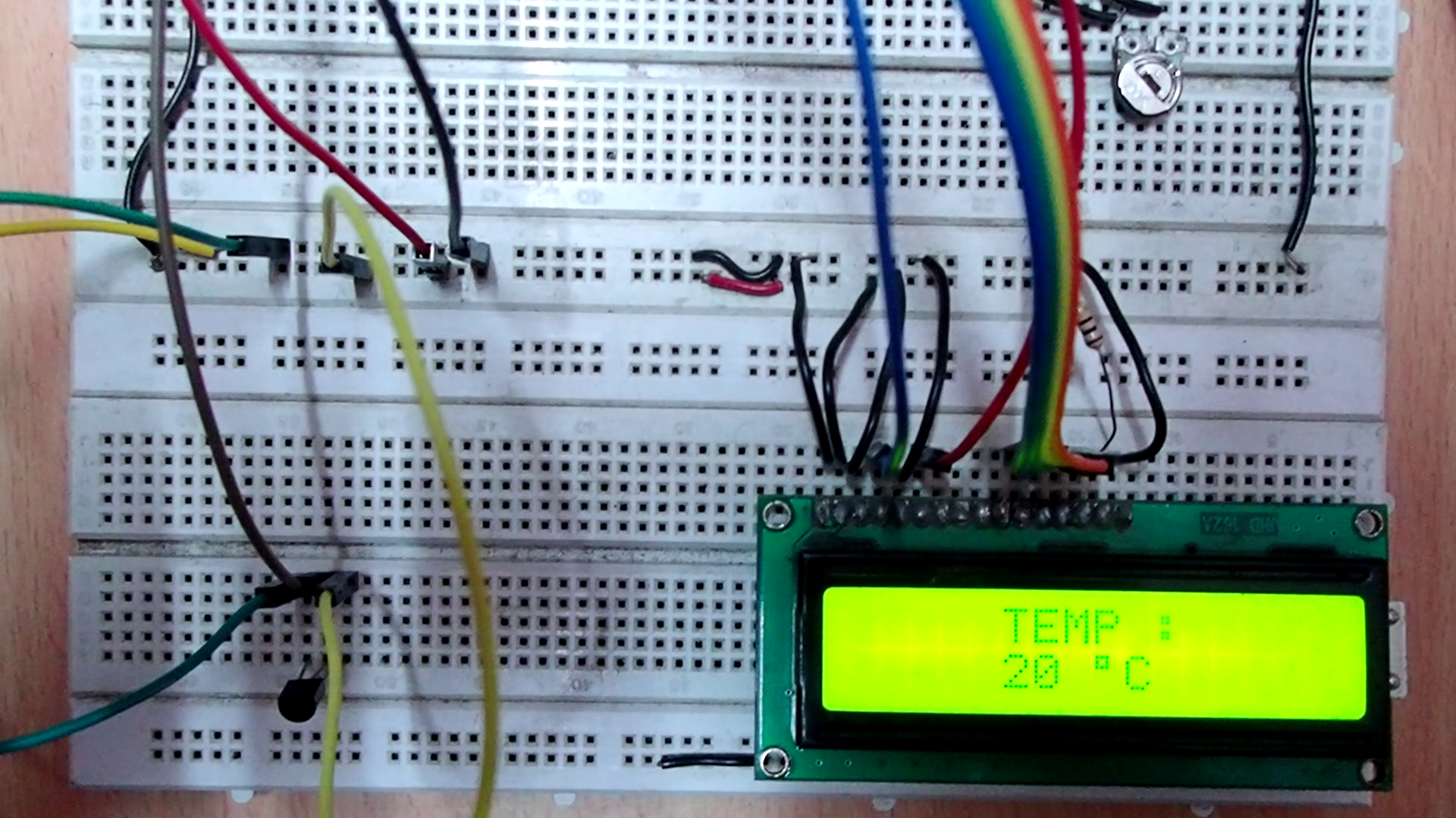
Circuit connections
To design a centigrade temperature sensor, Arduino is first interfaced with an LM35 sensor and a 16×2 LCD. Arduino will sense the analog voltage from the LM35 sensor and displays the temperature reading on the character LCD.
The LCD module used in this project is JHD162A. This is a 16×2 LCD module with 5×8 character dots. The LCD module has a 16-pin interface and is interfaced with Arduino in 4-bit mode.
Pin 1 (GND) and 16 (LED) of the LCD module is connected to ground while pin 2 (VCC) is connected to the VCC. Pin 15 (LED+) of the LCD module is connected to the VCC via a small-value resistor. Pin 3 (VEE) is connected to the variable terminal of a pot while the fixed terminals of the pot are connected to the VCC and ground. The R/W pin is connected to the ground as Arduino will only write the data to the LCD module.
The RS, EN, DB4, DB5, DB6, and DB7 pins of LCD are connected to pins 0, 2, 8, 9, 10, and 11 of Arduino UNO, respectively.
Terminal 1 of the LM35 sensor is connected to 5V DC and terminal 3 is connected to the common ground. Terminal 2 of the LM35 sensor is directly interfaced to the A0 pin of Arduino. The breadboard is supplied to the common ground and the 5V supply rail from one of the ground pins and 5V pin of the Arduino UNO, respectively.

Arduino sketch
How the project works
LM35 is a three-terminal, analog temperature sensor that runs on a single power supply. Its output pin is connected to the A0 analog input pin of Arduino UNO.
As Arduino can only sense unipolar voltages at its analog input pins, only a basic centigrade temperature sensor can be built using the LM35 sensor. This temperature sensor can detect positive centigrade temperatures from 2˚ to 150˚C. The LM35 sensor is supplied power from the Arduino’s 5V power output.
Arduino is programmed to read analog input voltage at the A0 pin. To accurately and precisely measure ambient temperature, multiple samples of the voltage output from the LM35 sensor are read at the A0 pin. The voltage sensed at the A0 pin is converted to a digital value by a built-in 10-bit ADC using Arduino.
This means each voltage sample will be read as a digital value, ranging from 0 to 1023. Multiple values sampled from the LM35 sensor must be averaged to derive a precise and accurate temperature reading.
As 5V is the default analog reference and ADC has a 10-bit resolution, the read digital value is converted to voltage using this equation:
Analog Voltage = (ADC Value *5)/1024
The read analog voltage is converted to the temperature reading using this equation:
Temperature (in ˚C) = LM35 Output Voltage (in Milli-Volt)/10
Once a temperature value is determined, it’s displayed on the character LCD, which is interfaced with Arduino in 4-bit mode.
Upon sampling a single value of analog voltage from the LM35 sensor, and before displaying it to the LCD, there was a large variation in the sensed temperature. This variation was still there after the analog voltage from the LM35 was sensed 100 times, and before displaying the mean measured value to the LCD.
When the sampling rate was increased to 900 voltage samples in a go, the variation in measured temperature was reduced to a few centigrade.
When the sampling rate was set to 950 voltage samples in a go, a constant and reliable temperature reading was obtained.
Finally, the prototype took 1,000 voltage samples from the LM35 sensor and displayed a mean of measured values to the LCD. Arduino required less than a millisecond to take these 1,000 voltage samples from the LM35.
The mean of measured voltage samples is used to derive the temperature value, which is displayed on the character LCD. A delay of one second is provided in each round of sampling the sensor data and displaying the derived temperature value on the LCD.
Programming guide
To begin, the LiquidCrystal.h library must be imported in the code. Then, an object defined by “lcd” is defined in the LiquidCrystal class.
#include <LiquidCrystal.h>
//LiquidCrystal lcd(RS, E, D4, D5, D6, D7);
LiquidCrystal lcd(0, 2, 8, 9, 10, 11);
A global variable of ‘LM35’ is defined to denote the analog input pin A0, where the LM35 sensor is connected. The variable ‘vin’ of the float type is defined to hold the current ADC reading. Also, the variable ‘vin_av’ of the float type is defined to hold the average of the ADC readings from the voltage samples.
The variable ‘tempc’ of the integer type is defined to calculate and store the temperature and the variable ‘i’ is defined to hold the counter value.
const int LM35 = A0;
float vin;
float vin_av = 0;
int tempc;
int i;
In the setup() function, the LCD is initialized to the 16×2 size using the begin() method, and the pin A0 is set to input by using the pinMode() function.
void setup()
{
lcd.begin(16, 2);
pinMode(LM35, INPUT);
}
In the loop() function, the LCD must first be cleared by using the lcd.clear() method. The cursor is set to column 5 of line 0 by using the setCursor() method. The string “TEMP :” is printed using the lcd.print() method. The cursor is set to column 5 of line 1 on the LCD.
Next, a for loop is run 1,000 times in which the voltage input from the LM35 sensor is sensed at pin A0 and added to the variable, which is defined to hold the mean of the measured samples in each loop repetition. After the loop is closed, the mean value of the measured samples is derived by dividing the variable ‘vin_av’ by 1,000.
This mean ADC value is then converted to the voltage by multiplying it by 5 and dividing it by 1,023 — as per the equation stated above. The voltage obtained is in Volts.
To get the temperature from this value, it’s multiplied by 1,000 to convert the voltage to Milli-volt, and then it’s divided by 10 (as per the temperature equation of LM35) to get the temperature reading.
The value of the derived temperature is printed on the LCD and a delay of one second is provided.
void loop()
{
lcd.clear();
lcd.setCursor(5, 0);
lcd.print(“TEMP : “);
lcd.setCursor(5, 1);
for(i=0;i<1000;i++){
vin = analogRead(LM35);
vin_av = vin_av + vin;
}
vin_av = vin_av/1000;
vin_av = (vin_av/1023)*5;
tempc = vin_av*100;
lcd.print(tempc);
lcd.print(” “);
lcd.print((char)223);
lcd.print(“C”);delay(1000);
}
The code of the loop() function will repeat until Arduino is shutdown. Therefore, Arduino will sample the voltage from the LM35 sensor 1,000 times and display the derived temperature reading on the LCD every second.
The temperature displayed on the LCD is the ambient temperature and indicates the temperature of the room in degrees centigrade. In this case, we’ve taken about 1,000 voltage samples from the LM35 at a time to get a constant and reliable temperature reading.
In the next tutorial, we’ll discuss interfacing the DHT-11 temperature and humidity sensor when using Arduino.
Filed Under: Arduino

Questions related to this article?
👉Ask and discuss on EDAboard.com and Electro-Tech-Online.com forums.
Tell Us What You Think!!
You must be logged in to post a comment.