In the previous tutorial, we discussed analog input when using Arduino. So far, we have covered four out of the five ways that controllers can interface and interact with other electronic components and devices. This includes digital output, digital input, analog output, and analog input.
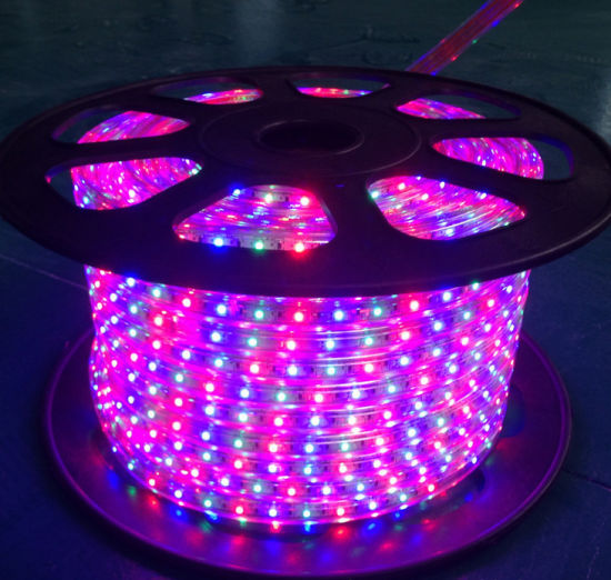
In this tutorial, we discuss how to interface RGB LEDs using Arduino. RGB LEDs are a combination of three LEDs — red, green, and blue — all packaged as one LED. These LEDs are used in several industrial applications, such as status/power indicators, plumbing fixtures, digital sign boards, LED rings, home decoration lights, and large outdoor displays.
By controlling the intensity of each individual LED, almost 16 million colors can be produced. RGB LEDs are used in the construction of direct-view, light-emitting diode (DV LED) screens that are widely used in the digital signage industry.
RGB LEDs
As mentioned in the intro, an RGB LED is a combination of three LEDs (red, green, and blue) in one package. Electronic display devices use an additive mixing of colors to produce different colors.
In additive mixing, red, green, and blue are the primary colors, which are colors that cannot be created by mixing other ones together. But, by mixing primary colors, all other colors can be generated.
The color receptors of the human eye are the most sensitive to these ones. So, by additive mixing these colors, the largest array visible to the human eye can be generated.
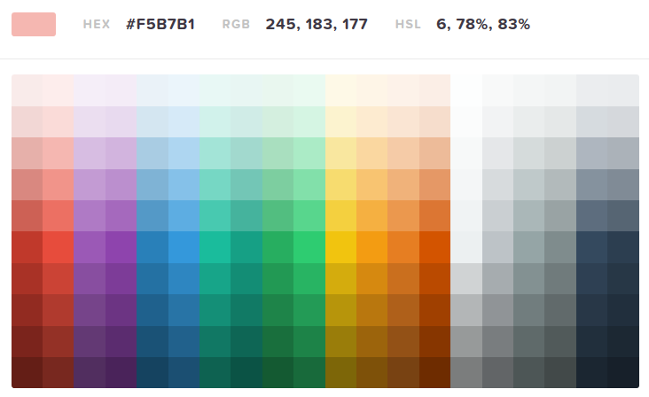
The color space that’s generated by mixing primary colors is called the RGB color space. Here are a few examples:
- When mixing red and green, shades of yellow and orange are created.
- When mixing green and blue, shades of cyan are created.
- When mixing red and blue, shades of purple and magenta are created.
- When mixing all three colors, shades of grey are created.
- When all three colors are fully saturated, white light is created.
- The absence of all three colors creates black light in the appropriate setup.
In a large outdoor DV LED display, each RGB LED works as a pixel.
By RGB LED, almost any color can be produced. So, let’s suppose that the intensity of each color is altered on an 8-bit scale, which would equate to 16,777,216 colors (256 x 256 x 256) or approximately 16 million colors that could be produced.
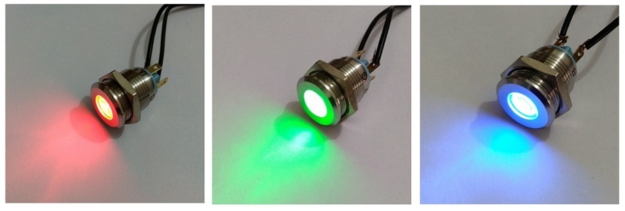
 In an RGB LED, three LEDs of red, green, and blue color are closely packaged. This is why when these LEDs emit light, the light is not viewed individually but as an additive mix of three lights.
The intensity of each color-LED can be controlled by applying the PWM signal to them. If the pulse width of that signal at each LED is changed by 8-bit values, the intensity of light of each LED also changes by the same scale.
Approximately 16 million different colors can be produced on an RBG LED.
Types of RGB LEDs
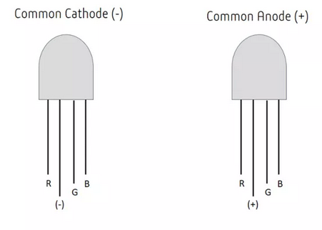
There are two types of RGB LEDs: Common-anode LED and Common-cathode RGB LED.
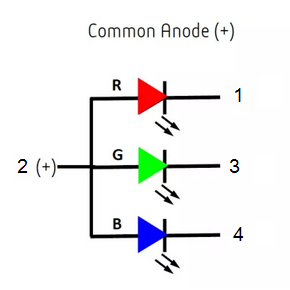
1. Common-anode LED
In common-anode LED, all three LEDs have a common anode but have different cathodes. These LEDs are interfaced to a controller such that the controller sinks current through them.
In this configuration, the PWM signal must be applied at the cathode terminals to vary the intensity of each LED. When the pulse width of the PWM signal increases, the intensity of the LED will decrease and vice-versa.
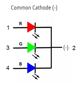
2. Common-cathode RGB LED
With the common-cathode RGB LED, all three LEDs have a common cathode but their anodes are different. These LEDs are interfaced to a controller such that the controller sources current to them.
In this configuration, the PWM signal must be applied at the anode terminals to vary the intensity of each LED. When the pulse width of the PWM signal increases, the intensity of the LED also increases and vice-versa.
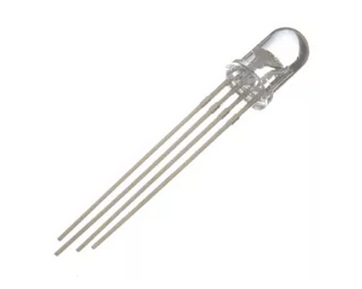
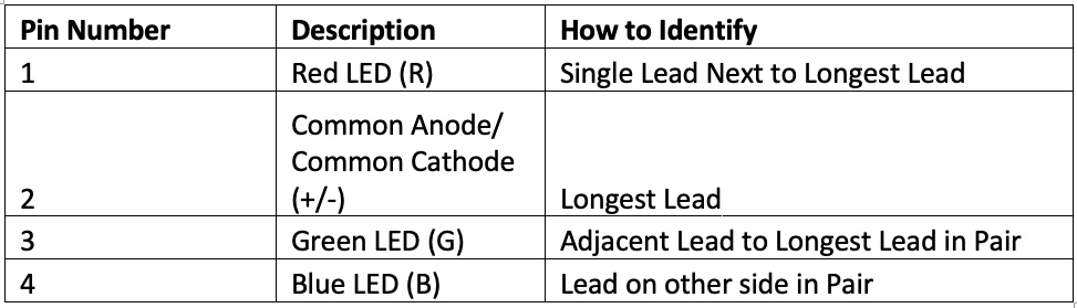
Both types of the RGB LEDs are four-terminal devices with this pin configuration:
The common-anode and common-cathode RGB LEDs can easily be distinguished by a multimeter. When using a multimeter, do so in continuity mode.
- Place the positive tip of the multimeter to the longest lead and the negative lead to any other terminal. If the respective red, green, or blue LED lights up, then it’s a common-anode LED.
- Place the negative tip of the multimeter to the longest lead and the positive lead to any other terminal. If the RGB LED lights up this time, then it’s a common-cathode RGB LED.
- If neither connection works, then one or more of the LEDs in the RGB LED may be damaged.
Non-linearity
It’s important to note that all three of the LEDs in the RGB LED have different VI characteristics. For example, they have different forward voltages and slightly different VI curves. This is because of the differences between the type of LEDs, according to the color they emit.
The electrical characteristics of red, green, and blue lights in the RGB LED are listed here:
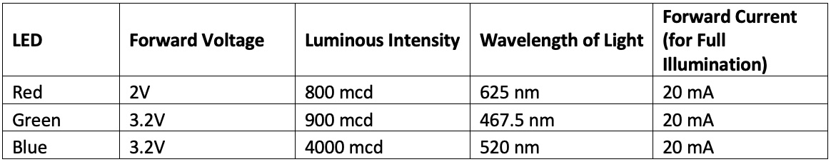
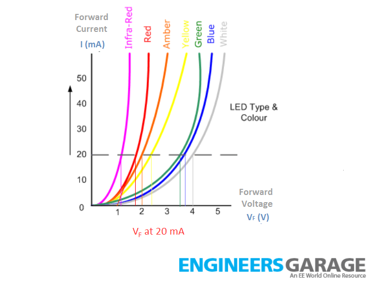
The VI curve of the LEDs is exponential and not linear. Also, the current through each LED peaks at different voltage levels and rises at different forward voltages. So, in a commercial application, all of these factors must be taken into account because the intensity of each LED has to be varied to produce different colors.
In commercial displays, the intensity of each LED is varied by the true analog signals that are supplied through the digital-to-analog converters. Furthermore, the non-linearity of the light intensity (or the units of lux) of the red, green, and blue LEDs is corrected by the gamma correction and other color calibration techniques.
For simplification, we will not take this non-linearity of the RGB LEDs into account. Rather, we will assume that the intensity of light of each color-LED varies equally against the applied forward voltage rising right off the 0V level. Also, the forward region curve is linear for all of the LEDs by the proportionality of one. This is only to simplify our controller program. But remember, this is just an assumption.
RGB LED applications
The RGB LEDs are used in several applications, such as the following:
1. Indicators
2. LED rings

3. Decorative lights
4. Plumbing fixtures

5. Digital sign boards and billboards

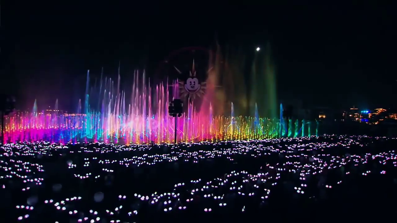
6. Outdoor lights and light shows
Controlling the RGB LED with Arduino
Most of the Arduino boards do not have a true analog output or, if they do, it only offers one or two channels. However, most of the Arduino boards can output PWM signals. For example, Arduino UNO can output a PWM signal using the analogWrite() function at pins 3, 5, 6, 9, 10, and 11.
Arduino boards can also output the PWM signals at any pin by using the timer/counters or by bit-banging.
The PWM signals are an approximation of the analog voltages. By applying a PWM signal, the same effect can be achieved on an RGB LED as if applying the analog voltage. As the PWM signal generated by using the analogWrite() function can vary the duty cycle, at an 8-bit scale, the RGB24 color profile can be mimicked by applying the PWM signals to red, green, and blue LEDs of the RGB LED.
This way, colors can be produced from an RGB LED that directly compares with the colors of the RGB24 color space — where each color is represented by 24-bit hexadecimal values.
The Arduino-based RGB LED driver recipe
In this recipe, we will design an RGB LED driver using Arduino. This RGB LED driver will not involve any corrections for the non-linearity of the red, green, and blue LEDs of an RGB LED.
Components required
1. Arduino UNO x1
2. RGB LED x1
3. 330 Ohms Resistor x1
4. Breadboard x1
5. Male-to-Male Jumper Wires or Connecting Wires
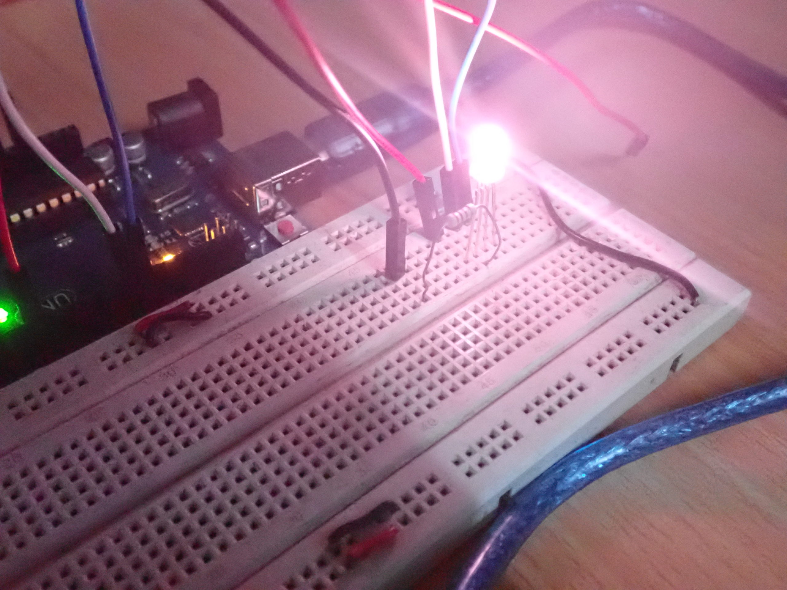
Circuit connections
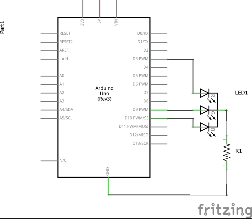
First, test whether your RGB LED is the common-cathode or the common-anode. The RGB LED used in this project is the common-cathode. So, the common-cathode terminal (the second terminal identified by the longest lead) must be connected to the ground via a series resistor of 330 Ohms.
The anode terminals of red, green, and blue LEDs of the RGB LED are connected to PWM pins 3, 9, and 10 of Arduino UNO. These pins can generate a PWM signal by using the analogWrite() function. The breadboard is supplied by common ground and 5V supply rail from one of the ground pins and 5V pin of the Arduino UNO, respectively.
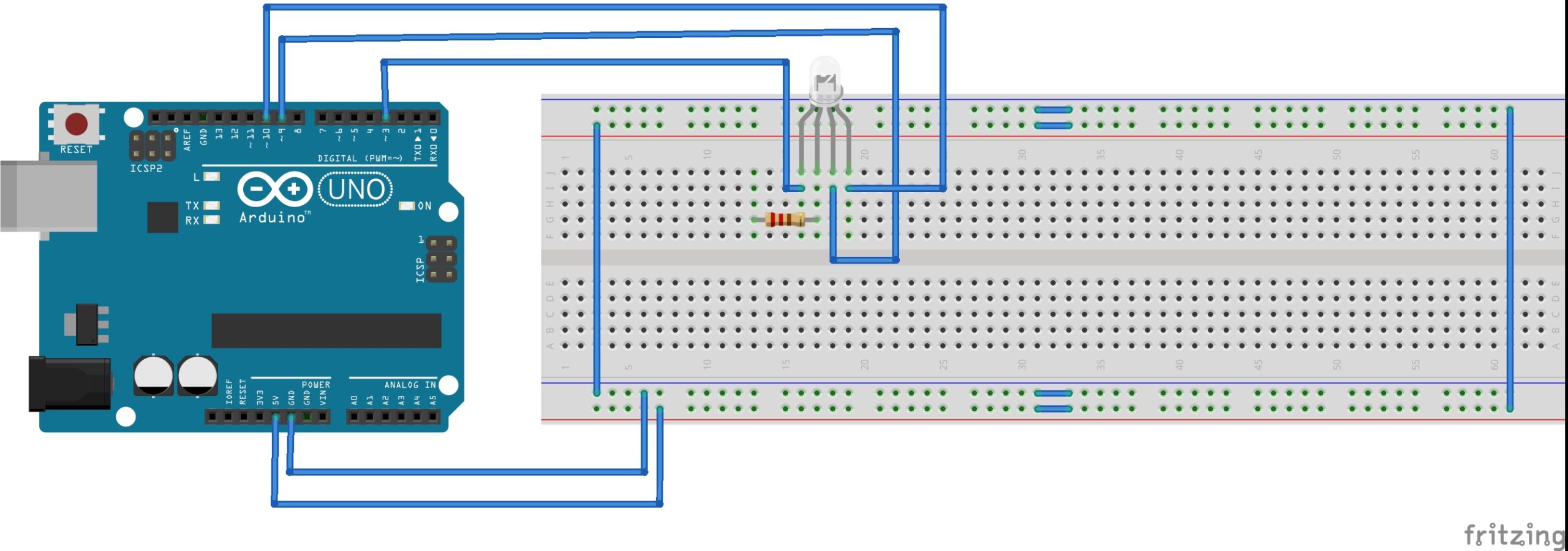
Circuit diagram
Arduino sketch
`
How the project works
The common-cathode RGB LED is interfaced with Arduino UNO, such that the Arduino’s PWM pins sources current to the color-LEDs of the RGB LED. From the PWM pins, a PWM signal is applied to the red, green, and blue LEDs by using the analogWrite() function.
The function outputs a PWM signal with a duty cycle that can be changed on an 8-bit scale. This means the intensity of each LED can be varied by 256 steps or on an 8-bit scale. So, the colors in the RGB24 color space can be produced on an RGB LED.
These colors can be directly compared with the colors of an RGB24 color space, where each color is represented by a 24-bit hexadecimal value. For example, to produce the pure red color on an RGB LED (where the color is represented by #FF0000), the intensity of the RGB lights should be 255 — so, 0 and 0 respectively.
As Arduino pins source the current to the color-LEDs, the intensity of the light of each LED increases by increasing the pulse width of the applied to the PWM signal.
If the intensity of the light of each LED is directly proportional to the pulse width (here we ignore the non-linearity of the RGB LED, such as the differences in the forward voltages and VI curves), then applying the PWM signals with the duty cycles of 100%, 0%, and 0% on the red, green, and blue LEDs will produce a pure red light.
For this to occur, however, the duty cycle of the PWM signals on the red, green, and blue LEDs must be defined by 255, 0, and 0, respectively.
Similarly, to get a pure green light, the PWM signals with the duty cycles defined by 0, 255, and 0 must be applied to the red, green, and blue LEDs. respectively.
To get a pure blue light, the PWM signals with the duty cycles defined by 0, 0, and 255 must be applied to the red, green, and blue LEDs, respectively.
To get pure white light, the PWM signals with the duty cycles defined by 255, 255, and 255 must be applied to the red, green, and blue LEDs, respectively.
When all of the LEDs are OFF, this will represent the black color. The other colors of the RGB24 color space can be produced by setting the duty cycle of the PWM signals to red, green, and blue LEDs by directly comparing their 24-bit hexadecimal values.
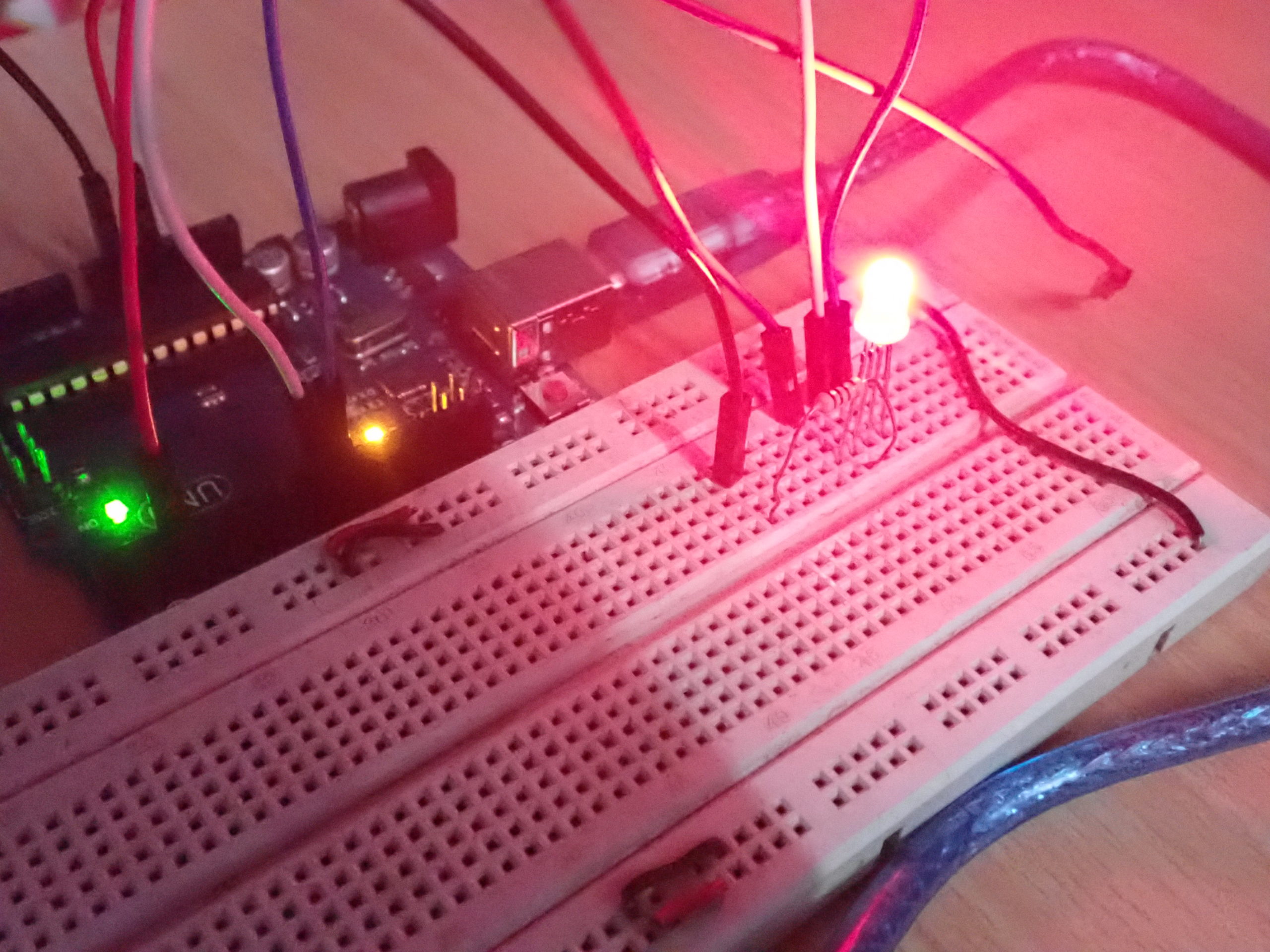
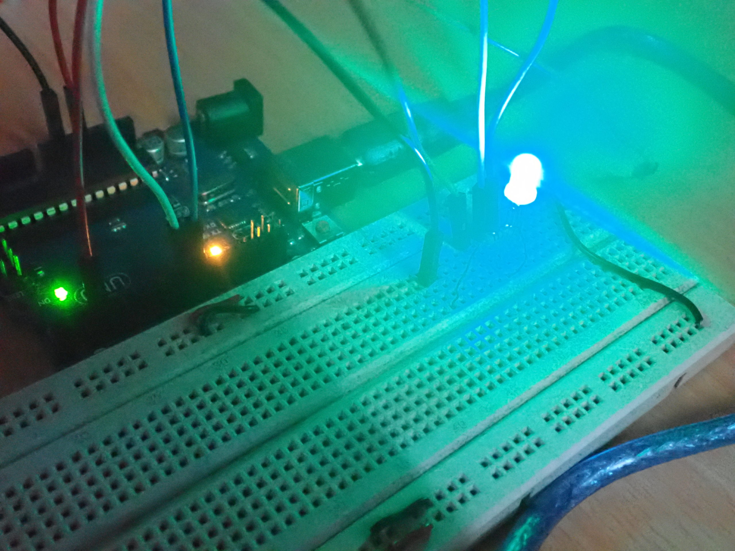
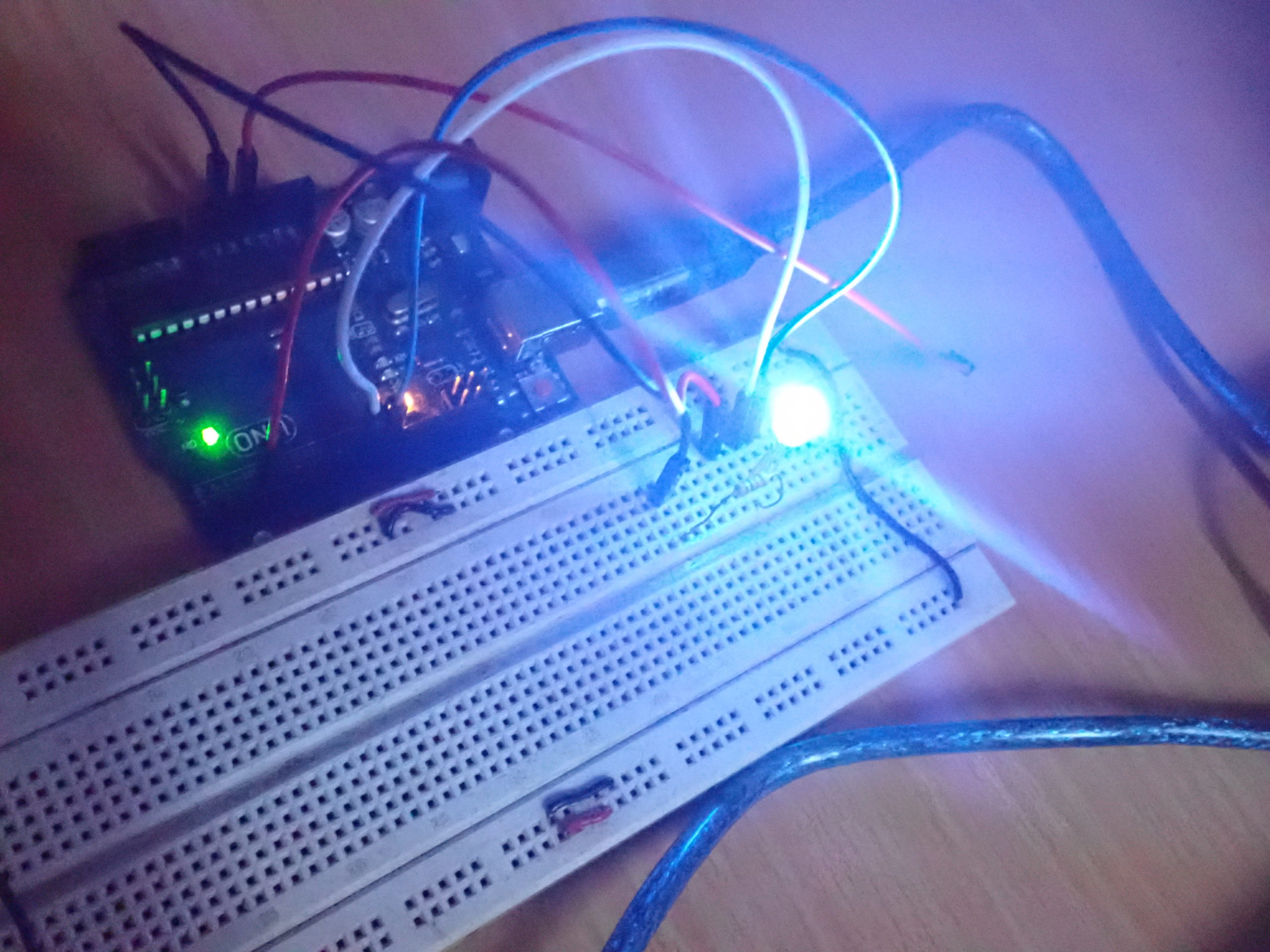
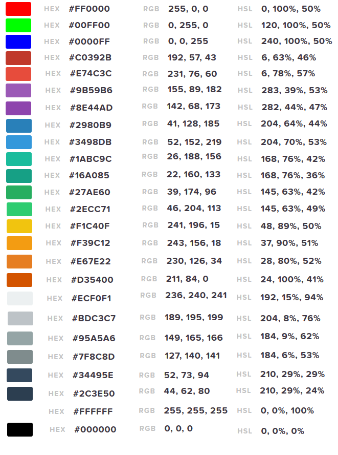
In this project, 25 different colors are generated from the RGB LED at an interval of one second each. These colors are listed below by their hexadecimal, RGB values, and the duty cycle values used to produce them.
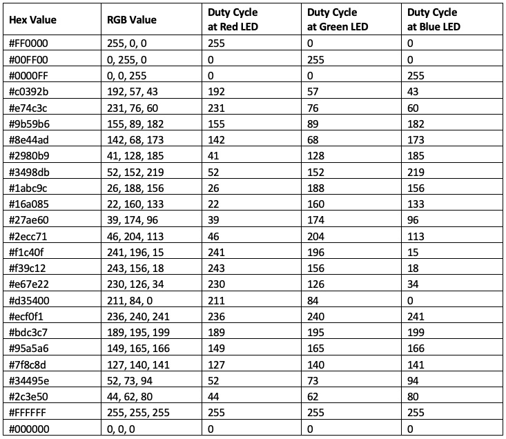
In this project, the following colors are produced on the RGB LED:
Programming guide
The 3, 9, and 10 pins that are connected to the R, G, and B terminals of the RBG LED are defined in the sketch as global variables R, G, and B. As we are using the analogWrite() function to generate the PWM signals at the terminals of the RGB LED, there’s no need to configure the pins using the pinMode() function. So, the setup() function is empty.
int R = 3;
int G = 9;
int B = 10;
void setup() {
}
In the loop() function, different colors are produced on the RGB LED by applying the PWM signals of the different duty cycles to the R, G, and B terminals of the RGB LED.
The duty cycle of PWM signals to the terminals of the RGB LED is directly proportional to the RGB values of these colors. These PWM signals are generated by calling the analogWrite() function. The delay() function is called to provide an interval of one second between the flashing each color.
For example, to produce a red color, this code is used:
analogWrite(R, 255);
analogWrite(G, 0);
analogWrite(B, 0);
delay(1000);
Similarly, to produce the light of the green color, this code is used:
analogWrite(R, 0);
analogWrite(G, 255);
analogWrite(B, 0);
delay(1000);
And to produce the light of the blue color, this code is used:
analogWrite(R, 0);
analogWrite(G, 0);
analogWrite(B, 255);
delay(1000);
To produce different shades in the RGB24 color space, the PWM signals with a duty cycle directly proportional to their RGB values are generated.
For example, to produce a shade with a hex value of #2ecc71, with an RGB value 46, 204, 113, this code is used:
analogWrite(R, 46);
analogWrite(G, 204);
analogWrite(B, 113);
delay(1000);
To produce a white color light, this code is used:
analogWrite(R, 255);
analogWrite(G, 255);
analogWrite(B, 255);
delay(1000);
To display the color black, all of the LEDs must be switched off by setting a duty cycle for all of the PWM signals to 0%. As all of the LEDs are switched off, this will show the color black in the appropriate settings — such as in the absence of any backlight in a display board.
analogWrite(R, 0);
analogWrite(G, 0);
analogWrite(B, 0);
delay(1000);
Note: The code of the loop() function keeps on repeating for an infinite number of times, flashing different colors on the RGB LED by the defined sequence until the Arduino UNO is powered on.
Try it yourself
In this RGB LED driver, the analogWrite() function is used to generate PWM signals to produce different colors on the RGB LED. As the duty cycle from the PWM signal can be varied using the analogWrite() function (between 0 to 100% over an 8-bit scale), it’s impossible to correct the non-linearity of the RGB LED.
However, if the PWM signals are generated by the timer/counter or the bit-banging (where the ON and OFF period of the PWM pulses are precisely controlled in microseconds), the PWM signals can be generated by corresponding the duty cycle with the forward voltages of the red, green, and blue LEDs.
The duty cycle of each PWM signal can be varied on an 8-bit scale for each LED by varying the voltage output between their forward bias voltage and the voltage at which their currents rise exponentially in their respective VI curves.
With a little more effort, the PWM signal can be generated to mimic the actual exponential curve of the VI characteristics of each LED by using the math library and an exponential function from it. You may need to check the datasheet of the RGB LED from the manufacturer to get the exact VI characteristic curves and each light of the particular RGB LED that follows.
In the next tutorial, we will discuss interfacing a seven-segment display (SSD) with Arduino.
Demonstration videos
You may also like:


Filed Under: Arduino, Tutorials

Questions related to this article?
👉Ask and discuss on Electro-Tech-Online.com and EDAboard.com forums.
Tell Us What You Think!!
You must be logged in to post a comment.