In the previous tutorial, we discussed interfacing RGB LEDs with Arduino. In this tutorial, you’ll learn how to interface seven-segment display (SSD) when using Arduino.
When interfacing with any kind of display device, Arduino and other controllers use digital output or serial communication. Driving SSDs by Arduino is as simple as driving an LED on it. The seven-segment display is made up of eight LED segments. These are used to display numbers.
In this tutorial, we will design a simple counter using an SSD that counts from 0 to 9 and will round off.
Seven-segment displays (SSDs)
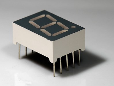
As mentioned in the introduction, an SSD is a unit that’s comprised of eight LED segments. Out of these eight LED segments, seven are bar-shaped and one is a dot.
There are 10 pins total on an SSD. Out of these 10 pins, two pins are common cathode or common anode, and the rest all are connected to opposite terminals of the LED segments.
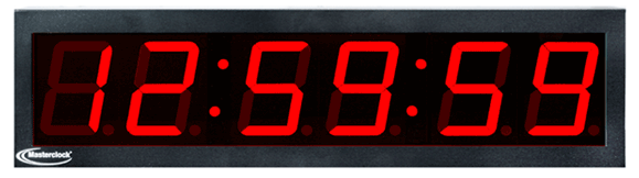
SSDs are used to display numbers. They are less costly and often employed as an alternative to character LCDs. These are used in embedded applications where the display only needs to show numbers. Take a digital clock, for example, which displays the time in numbers. It can be built using SSDs rather than an expensive LCD.
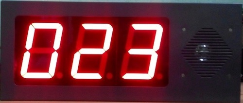
A token display board can also be built using SSDs as it only needs to display token numbers. Similarly, SSDs can be used in digital dashboards (such as the one on vehicle dashboards), which display numeric information (distance traveled, fuel efficiency, etc.).
Additionally, SSDs are used in several embedded and consumer applications where numeric data is displayed.
A few examples include:
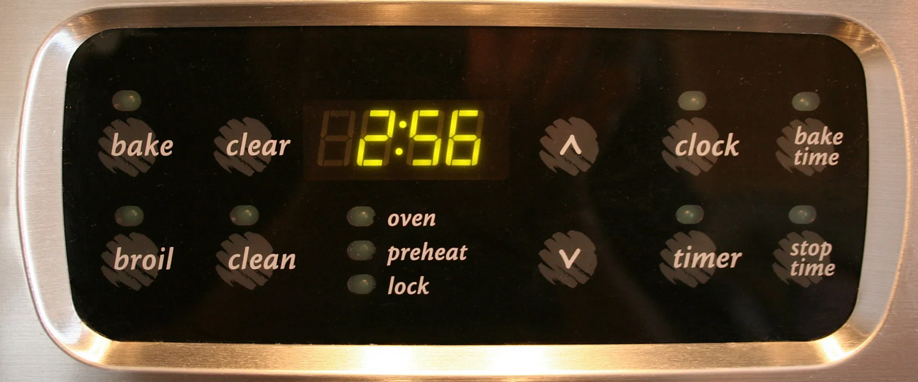
- The display timer for a microwave or a washing machine
- The temperature gauge on a space heater or air-conditioner
- The amount for a currency counting machine
- The numbers on a calculator, etc.

Types of SSDs
There are two types of SSDs:
1. Common-anode
2. Common-cathode
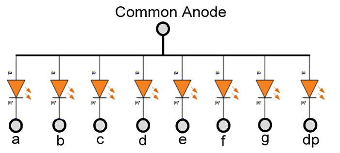
In the common-anode SSD, the anode of each of the LED segments has a common terminal while cathodes have separate terminals. To control each segment, the common anode is connected to the VCC and the cathode terminals are displayed as “logical LOW” to turn ON the segments and “logical HIGH” to turn them OFF.
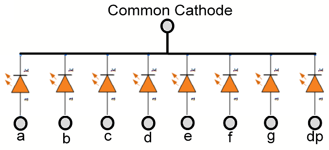
In the common-cathode SSD, the cathodes if each of the LED segments has a common terminal while the anodes have separate terminals. To control each segment, the common cathode is connected to ground and the anode terminals are displayed as “logical HIGH” to turn ON the segments and “logical LOW” to turn them OFF.
How SSD works
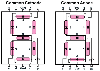
There are eight LED segments on an SSD, of which seven are bar-shaped and one is dot-shaped. The bar-shaped LED segments are designated by the alphabet letters “A” to “G” and the dot-shaped LED segment is designated by “DP.”
These LED segments are arranged on the SSD like this:
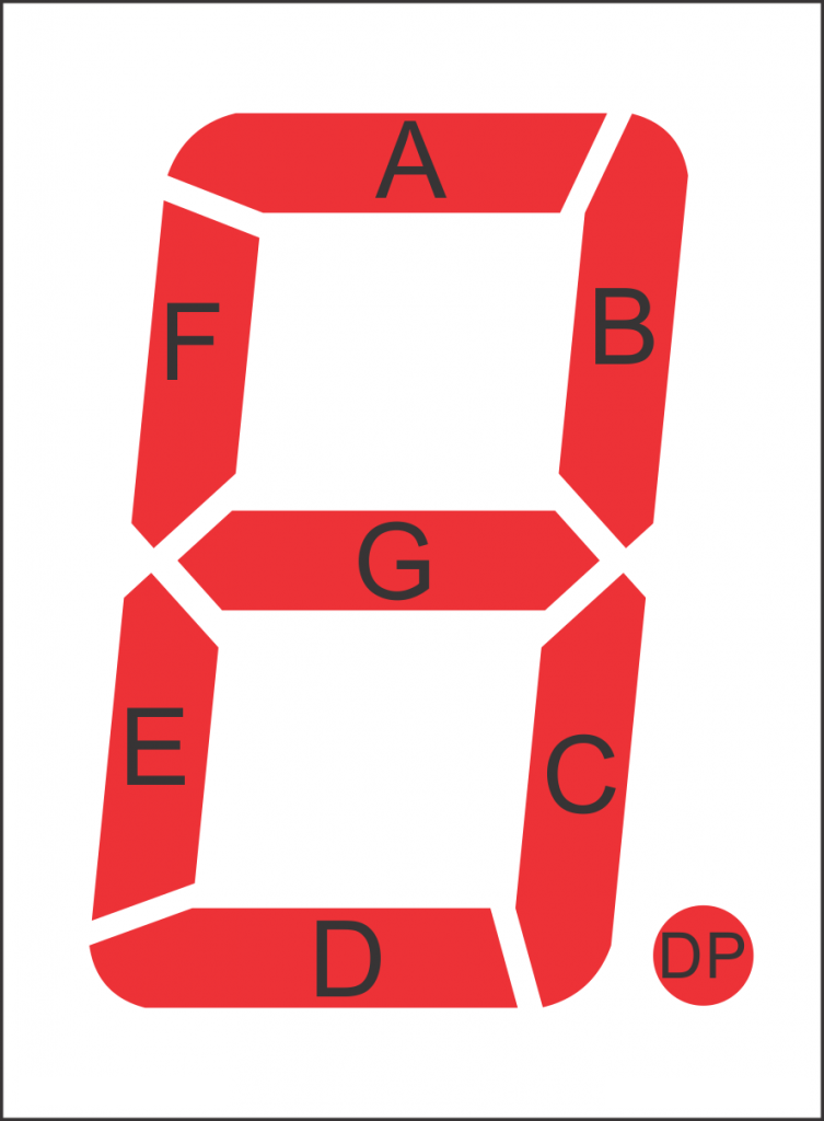
By lighting specific combinations of the LED segments, different decimal digits (0 to 9) and hexadecimal alphabets (A to F) can be displayed.

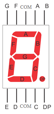
A seven-segment display has the following pin configuration:
SSDs have this internal circuit diagram:
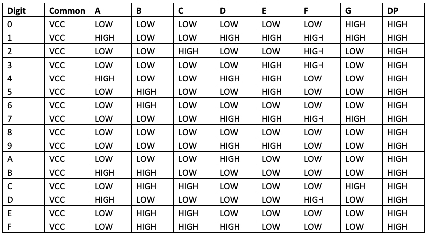
In the common-anode SSD, the common terminal is the anode of each of the LED-segments. To display different digits and hexadecimal alphabets, the LED segments of the common-anode SSD must be provided as digital logic.
This table offers a summarization:
In the common-cathode SSD, the common terminal is the cathode with all of the LED-segments. To display different digits and hexadecimal alphabets, the LED segments of the common-cathode SSD must be provided as a digital logic.
This table offers a summarization:
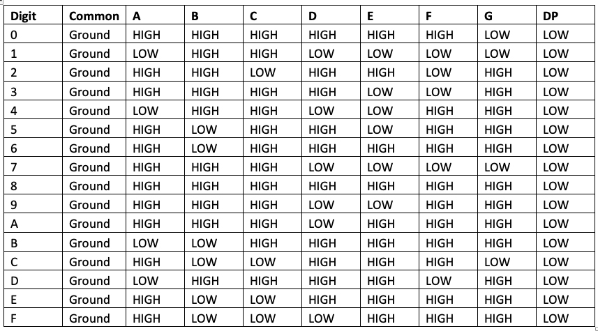
The logical table for the common-cathode is simply a reverse of the common-anode SSD. To protect the LED segments, it’s advisable to connect current-limiting resistors in series with each segment.
However, different LED segments may have different forward bias voltage. So, the resistors must be connected along each segment rather than connecting a single resistor to the common terminal. If a single resistor is connected to the common terminal, some of the LED segments may not glow because they may have a higher forward voltage. Alternatively, all of the segments may glow but with different light intensity.
The value of the resistor must be calculated according to the segment with the highest forward voltage.
The value of the resistor can be calculated using this equation:
RSeries = (VS – VLED)/ILED
Where,
RSeries = Value of resistor
VS = Source voltage
VLED = Highest forward voltage of LED segments
ILED = Current through LED segments
Let’s suppose the highest forward voltage is 1.7V, the source voltage is 5V, and the current required through the LED segments is 5 mA to 20 mA — or take the average 10 mA.
Then, the value of resistors will be:
R = (5-1.7)/10×10-3
= 330 Ohms
Driving SSD with Arduino
Interfacing SSD with Arduino is as simple as interfacing LEDs. The SSD can be treated like a collection of eight LEDs with a common anode or common cathode.
The instructions:
- For driving the common-anode SSD, the common terminal is connected to the VCC and the rest of the terminals are directly interfaced with Arduino’s digital I/O channels via series resistors. The channels must be set to LOW to turn ON the LED segments, and they must be set to HIGH to turn them OFF.
- For driving the common-cathode SSD, the common terminal is connected to the ground and the rest of the terminals are directly interfaced with Arduino’s digital I/O channels via the series resistors. In this case, the channels must be set to HIGH to turn ON the LED segments, and they must be set to LOW to turn them OFF.The digital I/O channels of Arduino output 5V/3.3V, and sources or sinks current up to 40 mA, which is sufficient to drive the LED segments. By turning the different combinations of LED segments ON and OFF, different digits (0 to 9) and alphabets (A to F) can be displayed.
- For driving more than one SSD together, a multiplexing technique is used. When there are many SSDs that have to be driven by a controller, the SSDs are interfaced via a demultiplexer or BCD-to-seven-segment decoder IC, such as SN7446AN.
Arduino-based SSD driver recipe
In this recipe, we will interface a seven-segment display using Arduino UNO and flash digits from 0 to 9 on it.
Components required
1. Arduino UNO x1
2. SSD x1
3. 330 Ohms Resistor x7
4. Breadboard x1
5. Male-to-Male Jumper Wires or Connecting Wires
Circuit connections
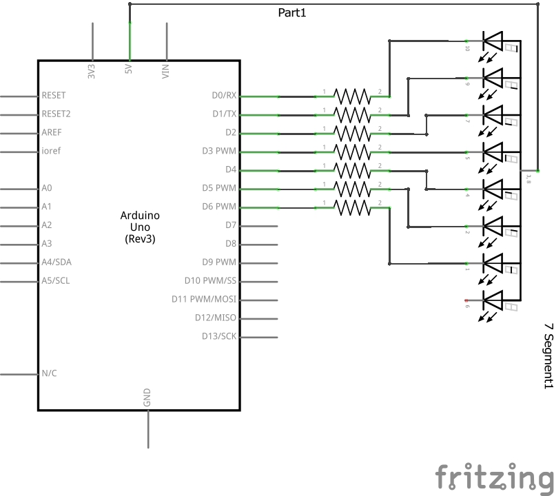
The SSD used in this project is a common-anode type. This means the common terminal of SSD is connected to 5V DC. The terminals A, B, C, D, E, F, and G of the SSD are connected to the digital I/O channels 4, 5, 6, 0, 1, 2, and 3, respectively.
Resistors of 330 Ohms are connected between each channel and the respective SSD terminals. The breadboard is provided as the common ground and 5V supply rail from one of the ground pins and 5V pin of the Arduino UNO, respectively.
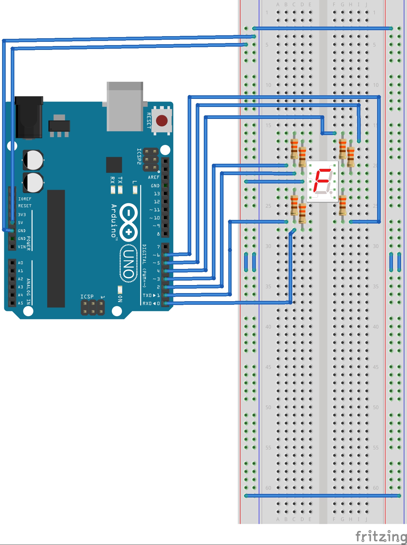
Circuit diagram
Arduino sketch
How the project works
To display different digits on the SSD, different combinations of the LED segments are switched ON and OFF at a time.
The SSD used in this project is a common-anode type. So, the common terminal of the SSD is connected to 5V DC and the rest of the terminals are interfaced with the Arduino channels via series resistors of 330 Ohms.
To display different digits, the logical table for a common-anode seven-segment is applicable.
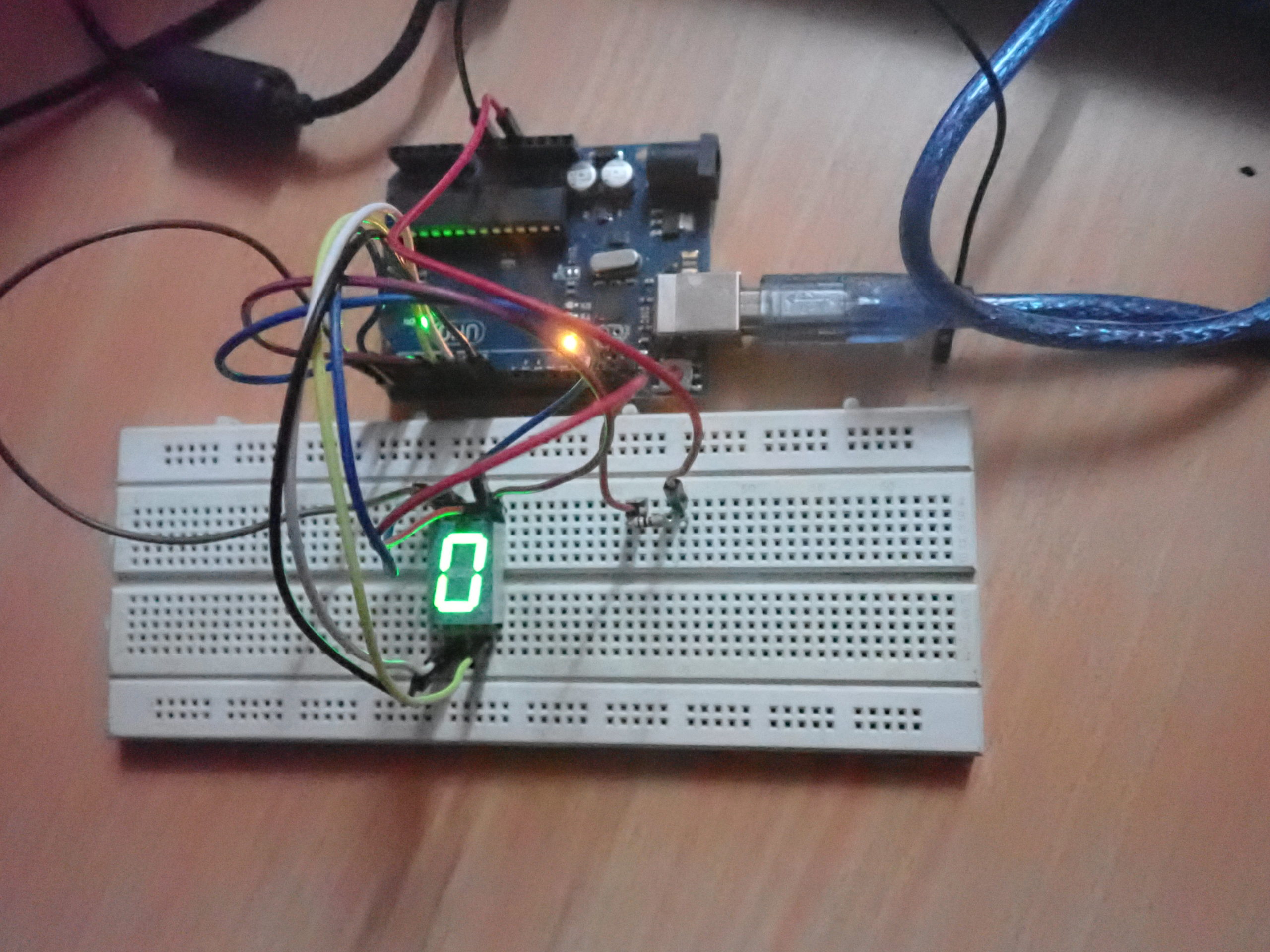
For flashing digits 0 to 9, the “0” is first displayed by turning the ON LED segments A, B, C, D, E, and F — while the LED segment G is turned OFF. After displaying “0” for one second, all of the LED segments are turned OFF for 300 milliseconds. Note: if all of the segments are not turned OFF, the LED segments will remain turned ON once they are switched back ON, and the successive digits will not display properly.
After displaying “0,” if all of the LED segments are not turned OFF, when displaying “1,” the SSD will still display “0.” It will display “8” when 2, 3, 4, 5, 6, 8, and 9 are flashed, and then “0” when the 7 is flashed. So, it is important to turn OFF all of the LED segments for a few milliseconds after displaying each digit.
So, for example:
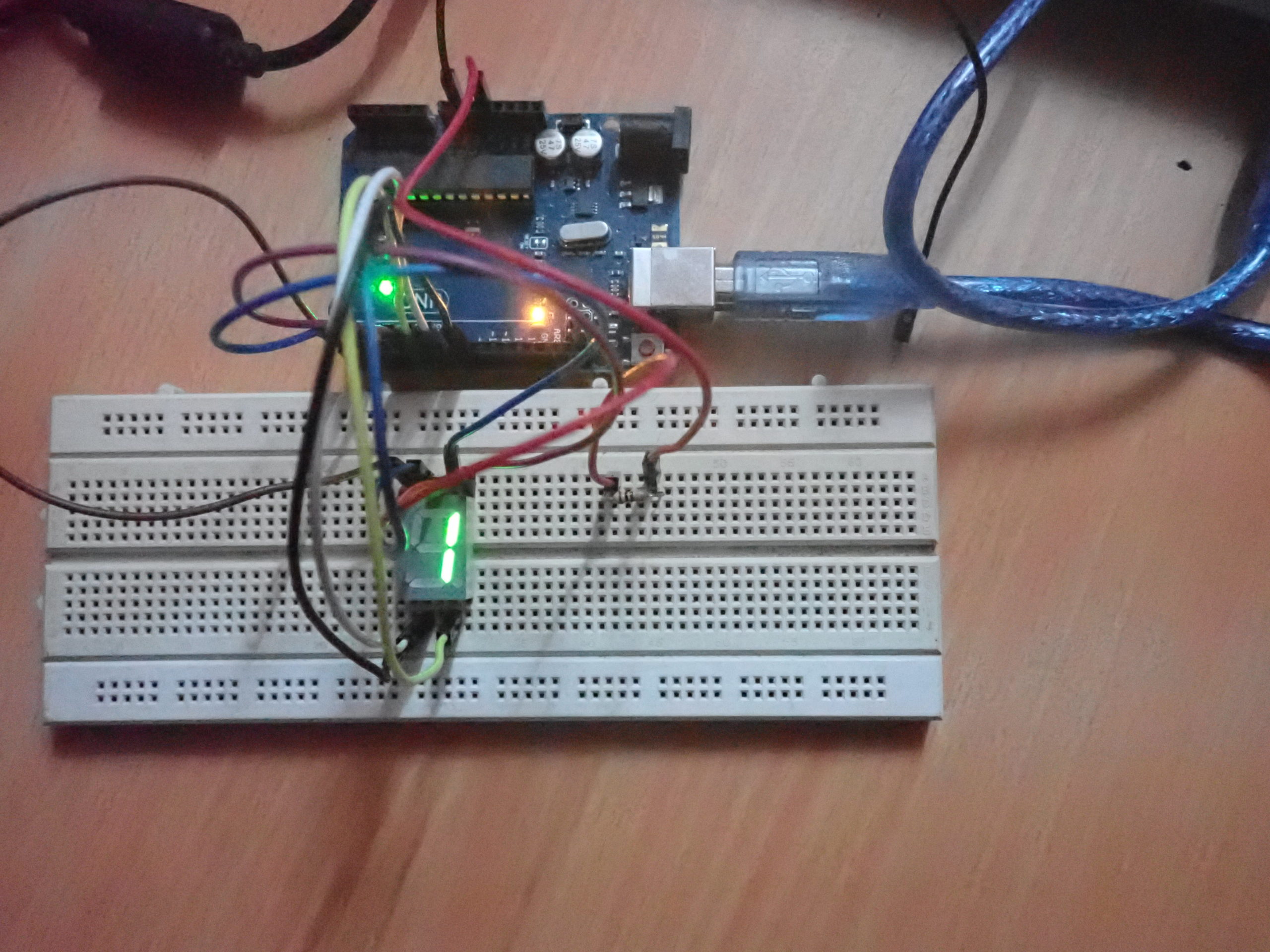
- For displaying “1,” the LED segments B and C are turned ON while the rest all are turned OFF.
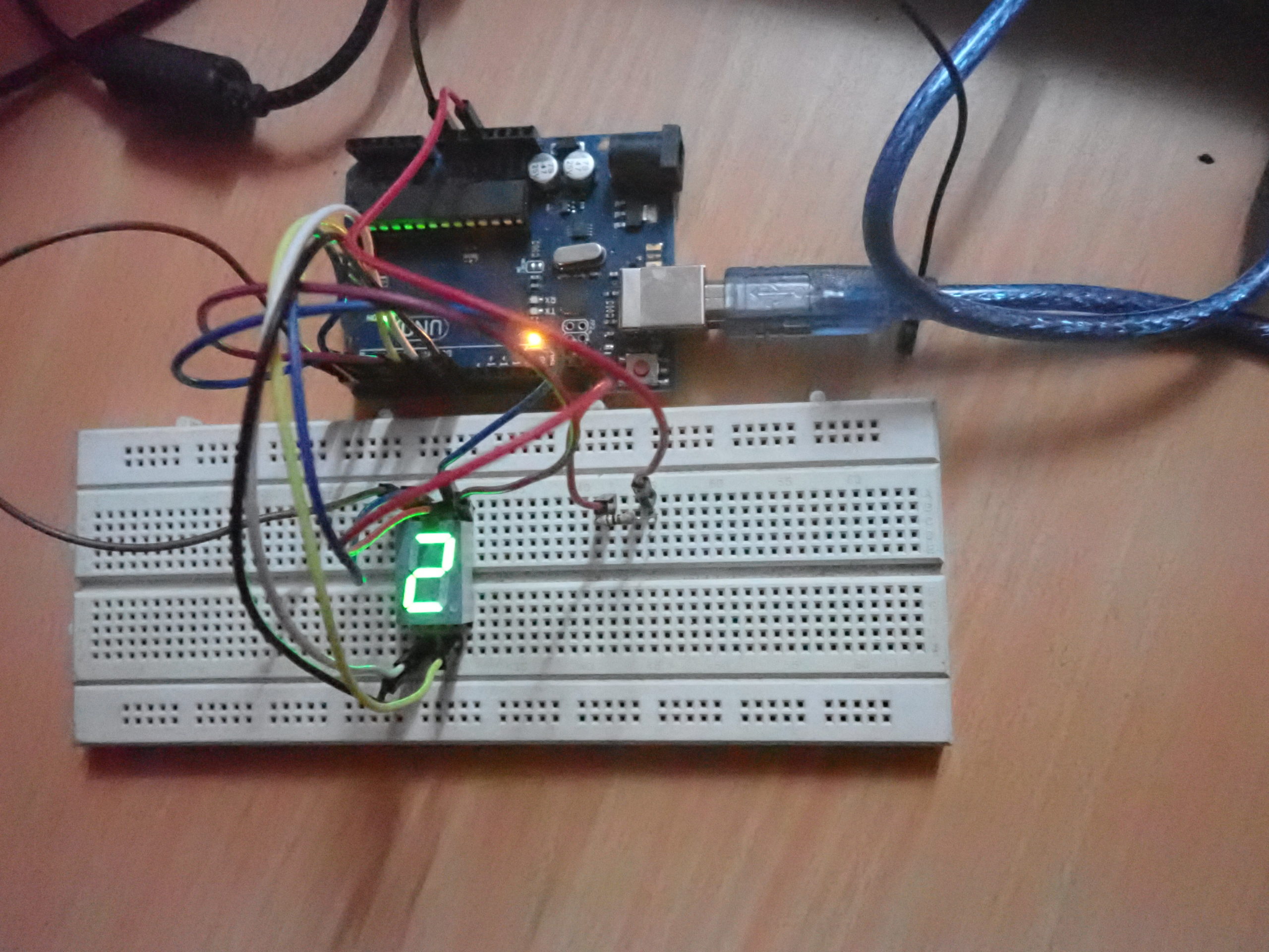
- For displaying “2,” the LED segments A, B, G, E, and D are turned ON while rest all are turned OFF.
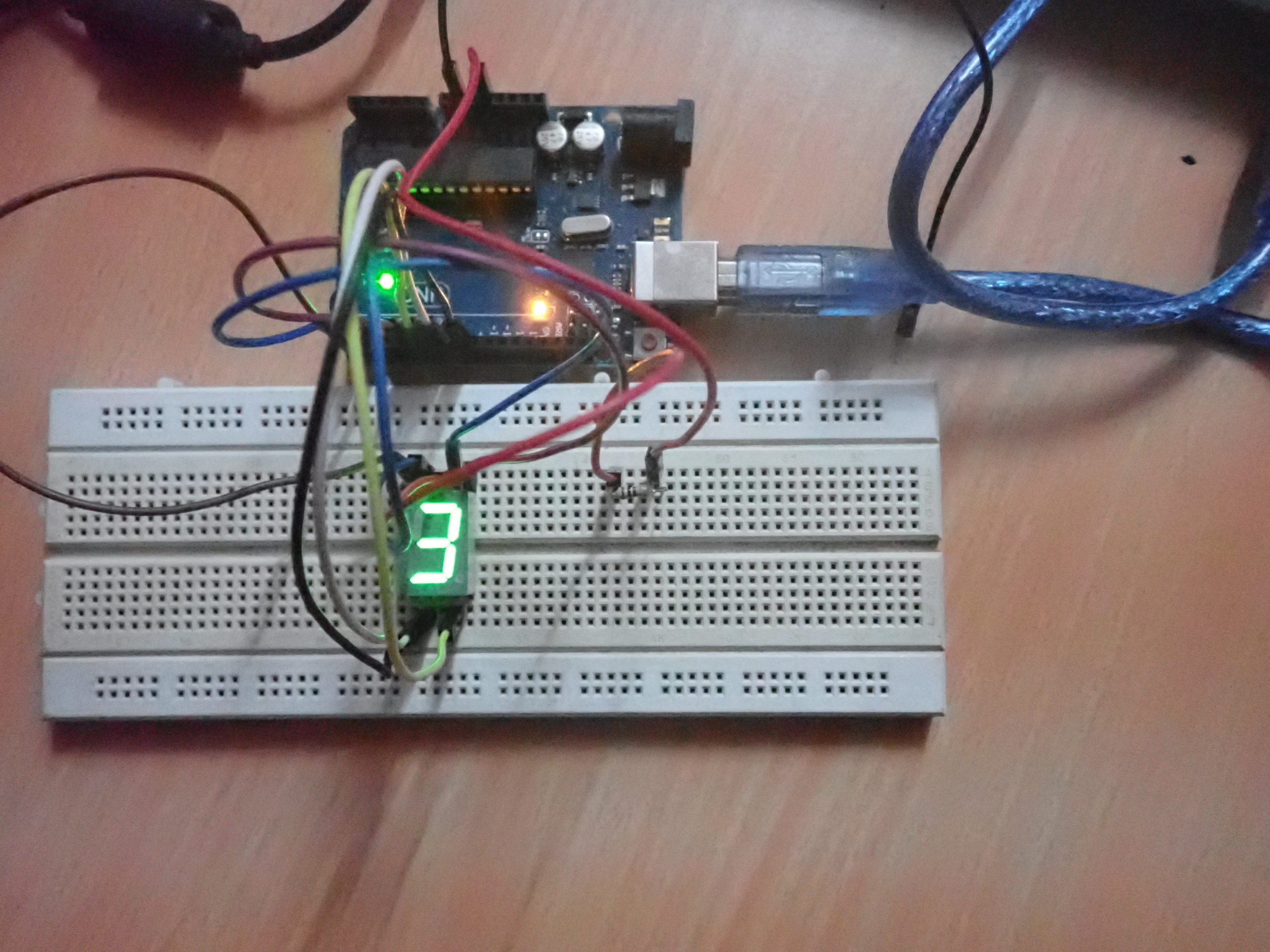
- For displaying “3,” the LED segments A, B, G, C, and D are turned ON while rest all are turned OFF.
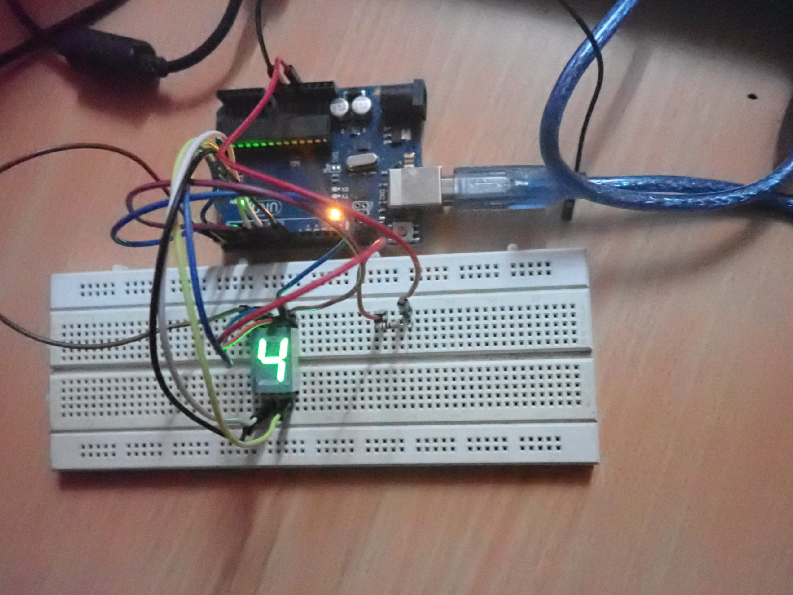
- For displaying “4,” the LED segments F, G, B, and C are turned ON while rest all are turned OFF.
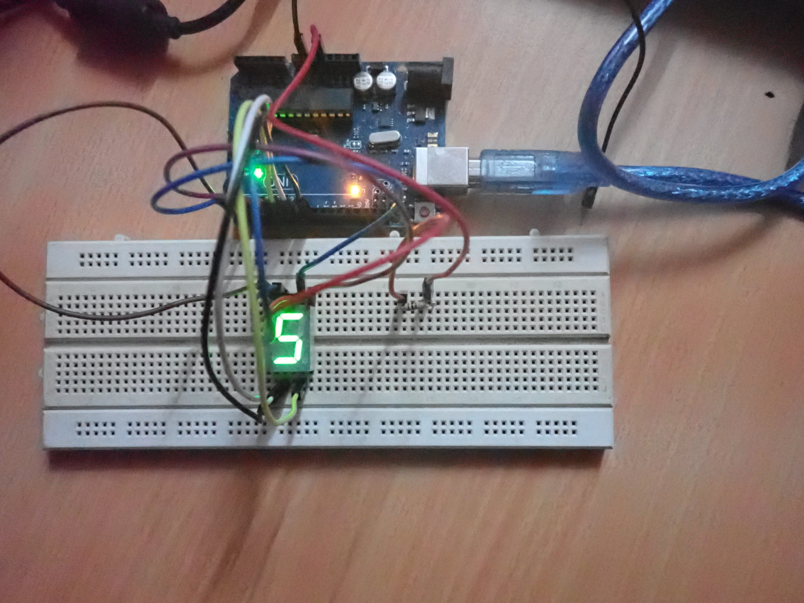
- For displaying “5,” the LED segments A, F, G, C, and D are turned ON while rest all are turned OFF.
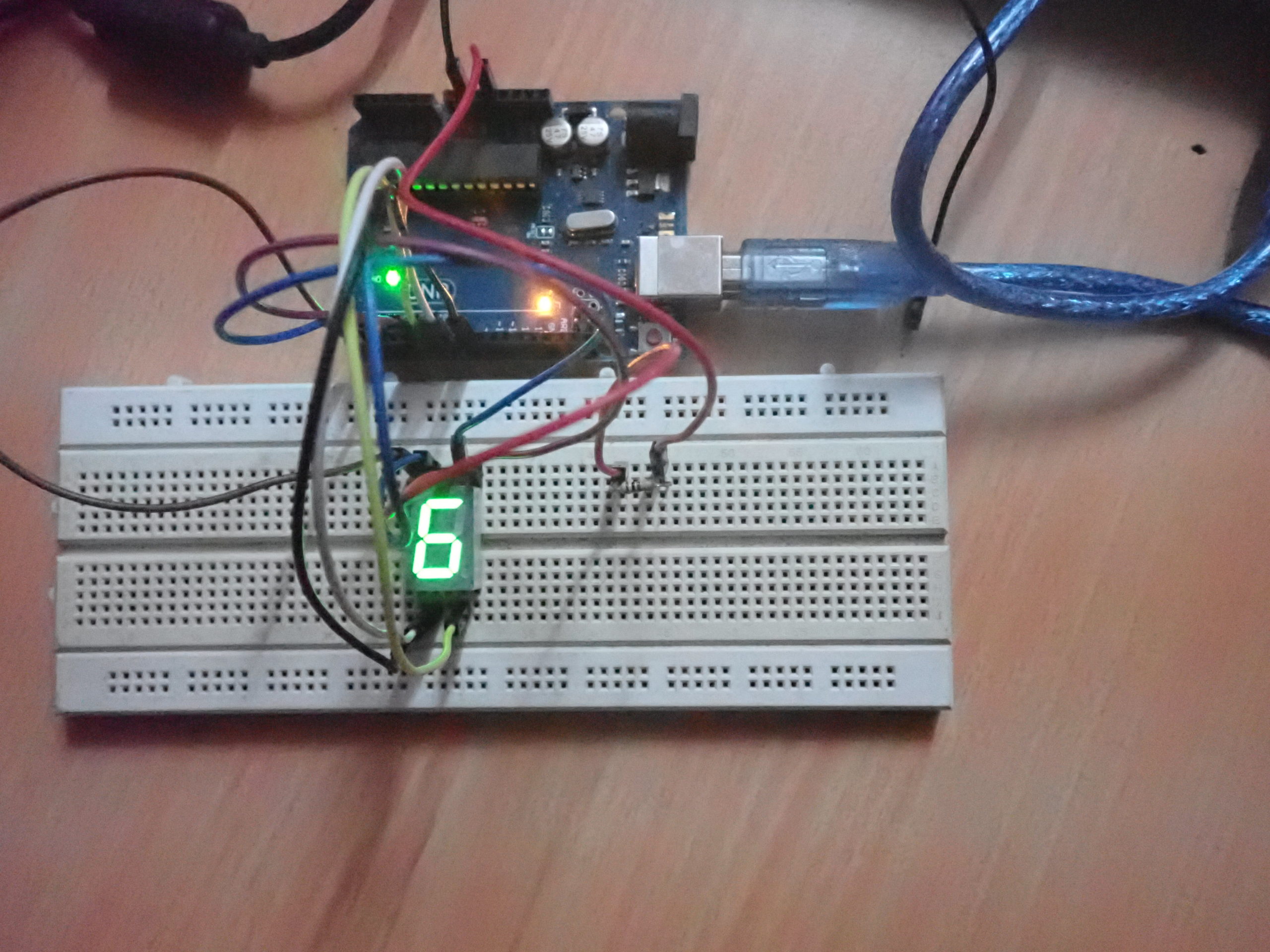
- For displaying “6,” the LED segments A, F, G, E, D, and C are turned ON while rest all are turned OFF.
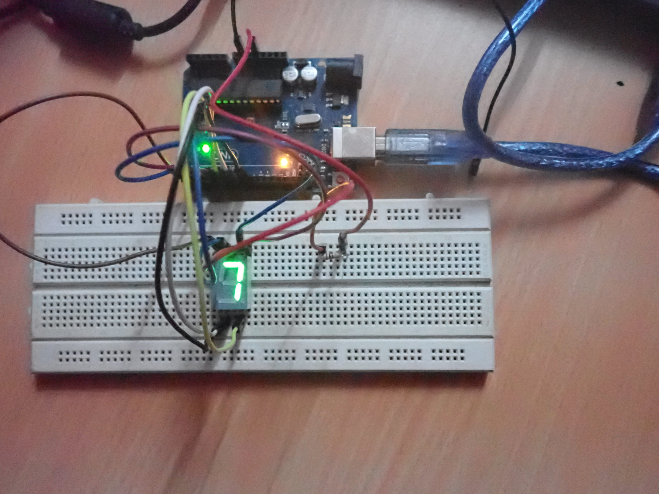
- For displaying “7,” the LED segments A, B, and C are turned ON while rest all are turned OFF.
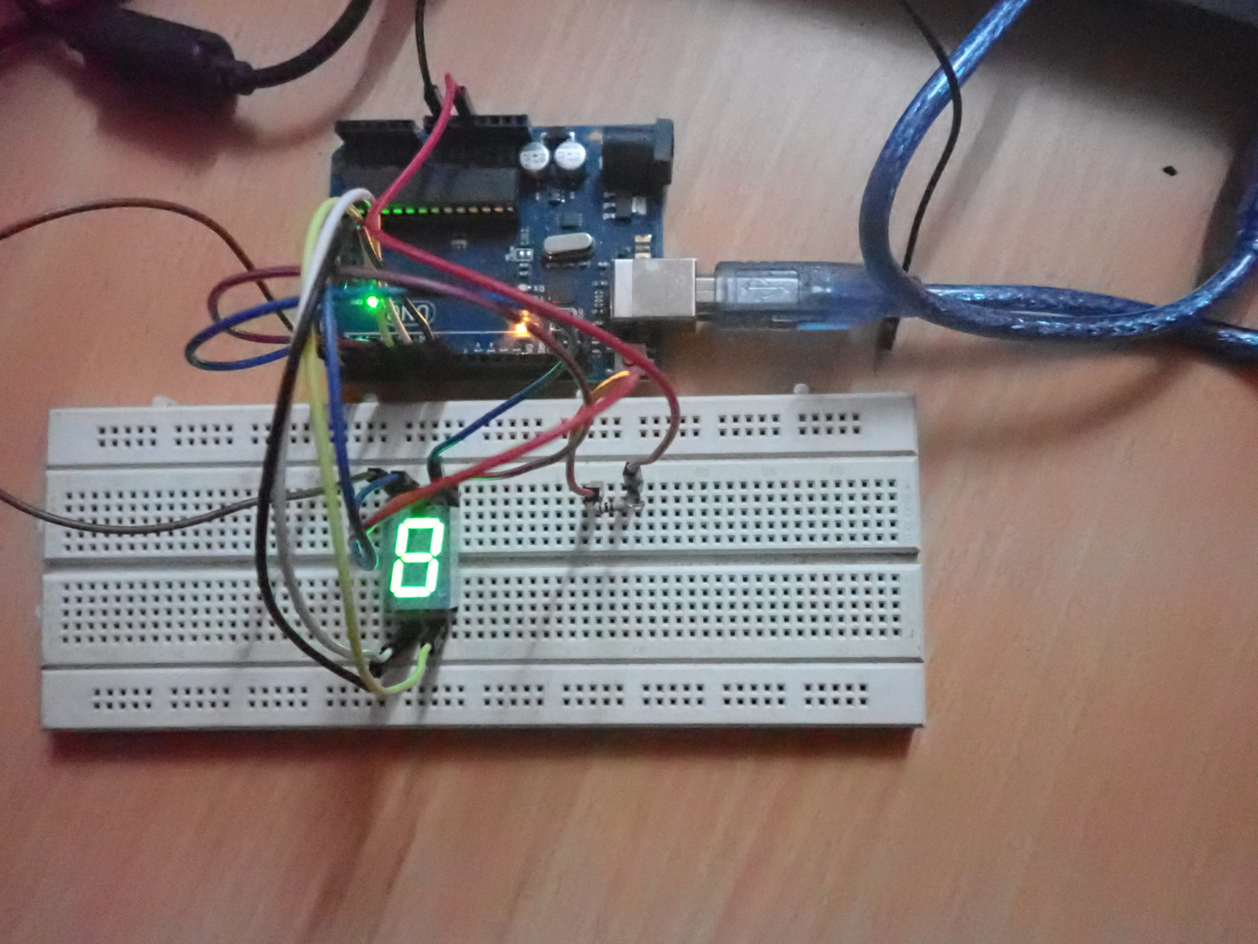
- For displaying “8,” all of the LED segments (except DP) are turned ON.
- For displaying “9,” the LED segments A, B, F, G, and C are turned ON while rest all are turned OFF.
All of the LED segments are turned OFF for 300 milliseconds after displaying a digit for one second. As the Arduino keeps repeating its code, the display of the digits 0 to 9 will keep repeating until Arduino is shut down.
Programming guide
The Arduino sketch begins by defining the global variables, which correspond to the SSD terminals that are connected to the Arduino channels.
int g = 3;
int f = 2;
int a = 4;
int b = 5;
int c = 6;
int d = 0;
int e = 1;
In the setup() function, these channels are set as digital output by using the pinMode() function.
void setup() {
pinMode(a, OUTPUT);
pinMode(b, OUTPUT);
pinMode(c, OUTPUT);
pinMode(d, OUTPUT);
pinMode(e, OUTPUT);
pinMode(f, OUTPUT);
pinMode(g, OUTPUT);
}
In the loop() function, the logic-to-flash digits of 0 to 9 are written on the SSD. As the SSD used in this project is a common-anode, on writing “logical HIGH” to a channel, the respective LED segment turns OFF; and on writing “logical LOW” to a channel, the respective LED segment turns ON.
First, all of the LED segments are turned OFF by writing “logical HIGH” to all of the interfaced channels using the digitalWrite() function. A delay of 300 milliseconds is provided after using the delay() function.
void loop() {
digitalWrite(a, HIGH);
digitalWrite(b, HIGH);
digitalWrite(c, HIGH);
digitalWrite(d, HIGH);
digitalWrite(e, HIGH);
digitalWrite(f, HIGH);
digitalWrite(g, HIGH);
delay(300);
Next, the first digit “0” is displayed by turning the ON LED segments A, B, C, D, E, and F, which is done by writing “logical LOW” on the respective channels.
A delay of one second is provided by calling the delay() function, so that the digit “0” remains displayed on the SSD for one second.
digitalWrite(a, LOW);
digitalWrite(b, LOW);
digitalWrite(c, LOW);
digitalWrite(d, LOW);
digitalWrite(e, LOW);
digitalWrite(f, LOW);
delay(1000);
After displaying “0,” all of the LED segments are turned off for 300 milliseconds.
Then, digit “1” is displayed for one second by only turning the ON LED segments B and C.
digitalWrite(a, HIGH);
digitalWrite(b, HIGH);
digitalWrite(c, HIGH);
digitalWrite(d, HIGH);
digitalWrite(e, HIGH);
digitalWrite(f, HIGH);
digitalWrite(g, HIGH);
delay(300);
digitalWrite(b, LOW);
digitalWrite(c, LOW);
delay(1000);
Similarly, the other remaining digits (from 2 to 9) are displayed for one second each by selectively turning ON and OFF the LED segments.
After displaying each digit for one second, all of the segments are turned OFF for 300 milliseconds. And, after displaying digit “9,” the code written in the loop() function keeps on repeating — flashing each digit (from 0 to 9) for one second each, for an infinite number of times.
In the next tutorial, we will discuss multiplexing SSDs.
Demonstration video
You may also like:


Filed Under: Arduino, Tutorials

Questions related to this article?
👉Ask and discuss on EDAboard.com and Electro-Tech-Online.com forums.
Tell Us What You Think!!
You must be logged in to post a comment.