In the previous article, we looked at various types of capacitors. Now, let us discuss selecting a capacitor for a given application. Generally, selecting a capacitor is not a daunting task unless you have specific circuit requirements. Engineers often have a nominal capacitance derived for a circuit at hand or have to use capacitance with an IC or an active component. Most ICs (like 555, microcontroller ICs, etc.) have recommended values of capacitance specified in their datasheets for different applications.
Unless there are specific circuit requirements, and if the required capacitance is in Picofarad, a ceramic capacitor can be used. If the required capacitance is in Nanofarad, MLC (Multilayer Ceramic) capacitors can be blindly trusted. If the capacitance necessary is in Microfarad, aluminum electrolyte capacitors are a common choice. For a wider temperature range and robustness, glass and mica capacitors can be used.
Apart from nominal capacitance, the voltage rating is the second most important parameter that must be essentially factored in. The capacitor’s voltage rating should always be at least 1.5 times or twice the maximum voltage it may encounter in the circuit. Capacitors are not as reliable as resistors. They get easily damaged once the applied voltage nears their maximum rating.
If a circuit has specific requirements, many other factors will need consideration. Different types of capacitors are preferable for particular circuits and applications. The preferred applications of different types of capacitors are summarized in the following table:

Apart from the suitability of different capacitors for specific applications, other important factors that may need to consider include the following:
- Tolerance – It must be checked if the working of the circuit depends on precision capacitance. A capacitor with the lowest tolerance should be used if it requires narrow capacitance. The capacitance of a capacitor will never vary beyond its rated tolerance unless it gets damaged due to excessive voltage or environmental conditions.
- Operating temperature range and temperature coefficient – If the circuit is temperature-sensitive or capacitance should not vary beyond a limit over a range of temperatures, its operating temperature range, and temperature coefficient must be considered. The extent of change in capacitance should be calculated based on the temperature coefficient and temperature curve. The temperature sensitivity of a circuit can also be dealt with by using capacitors of positive and negative temperature coefficients together. In that case, the maximum variation of capacitance over a range of temperatures must be calculated.
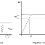
- Frequency Dependence – Many capacitors have their capacitance dependent on the frequency and may not be suitable for a specific range of frequencies. Depending upon the circuit, the frequency dependence of the capacitance should be essentially considered.
- Operating Losses – Operating losses can be an important factor where circuits need energy efficiency (like battery-operated circuits). For such circuits, a careful selection of capacitors should be made considering their dissipation factor (typical loss of energy in percentage), dielectric absorption, leakage current or insulation resistance, and self-inductance. All these losses must be minimized to improve the efficiency and battery life of the circuit.
- Ripple Current and Pulse Voltages – These are quite important checks. The circuit must be manipulated for pulsating voltages and maximum ripple current. A capacitor with an appropriate ripple current and working voltage rating should be chosen.
- Polarity and Reverse Voltage – If an electrolyte capacitor is used in the circuit, it must be connected in the correct direction. Its reverse voltage rating should be at least twice the possible reverse voltage in that branch of the circuit.
Standard values of capacitors
Capacitors also come available in standard values according to E-series like the resistors. For learning more about standard values of resistors, capacitors, inductors, and Zener diodes, check out the following article, “Basic Electronics 08 – Reading Value, Tolerance and Power Rating of Resistors”.
There are fewer standard values for capacitors compared to resistors. Generally, capacitors come available only in the E-6 Series of standard values (10, 15, 22, 33, 47, and 68) followed by a specified number of zeros.
Series and parallel combination of capacitors
It may not be possible to have the exact value of desired capacitance in standard E-series. In such cases, a series or parallel combination of capacitors can be used to get the desired capacitance in the circuit. When capacitors are connected in series, the equivalent capacitance is given by the following equation:
1/Cseries = 1/C1 + 1/C2 + 1/C3 + . . . .
When capacitors are connected in parallel, the equivalent capacitance is given by
CParallel = C1 + C2 + C3 + . . . .
The equation for a series combination of capacitances is derived from the fact that the sum of voltage drops across all capacitances connected in a series will be equal to the applied voltage while current through them shall remain the same. The equation for a series combination of capacitances is derived in the following way:
VTotal = VC1 + VC2 + VC3 + . . . .
1/CSeries * ∫i.dt = 1/C1 * ∫i.dt + 1/C2 * ∫i.dt + 1/C3 * ∫i.dt + . . .
1/Cseries = 1/C1 + 1/C2 + 1/C3 + . . . .
The equation for the parallel combination of capacitances is derived from the fact that the sum of the currents through all the capacitances connected in parallel will be equal to the total current while the voltage across them shall remain the same. The equation for the parallel combination of capacitances is derived in the following way:
I = i1 + i2 + i3 + . . . .
CParallel * dV/dt = C1 * dV/dt + C2 * dV/dt + C3 * dV/dt + . . . . .
CParallel = C1 + C2 + C3 + . . . .
Reading resistor packages
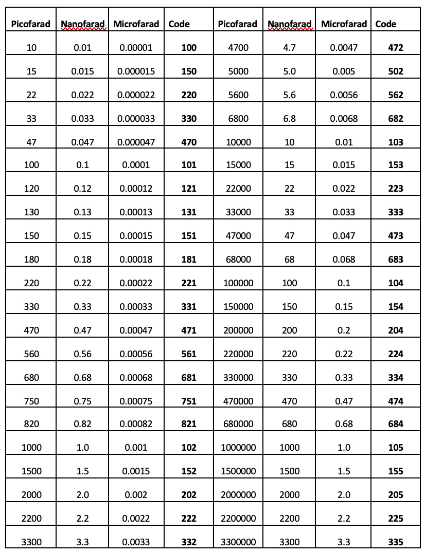
In the past, color codes and different types of numerical codes were used to indicate value, tolerance, and working voltage of capacitors. Today, the capacitance, tolerance, and working voltage are printed on the body of the capacitors or indicated by BS1852 standard or BS EN 60062 standard codes. In these coding systems, the value, tolerance, and working voltage of the capacitor are indicated by two -or three-digit numerical codes followed by a letter. The value of capacitance is always indicated in Picofarads. If it is a two-digit code, it is the direct value of capacitance in Picofarads, and if it is a three-digit code, the first two digits indicate a number (E-6 Series), and the third digit indicates a multiplier giving the final value of capacitance in Picofarads. A letter may be used to indicate the tolerance of the capacitor. The tolerance indicated by different letters has been summarized in the following table:
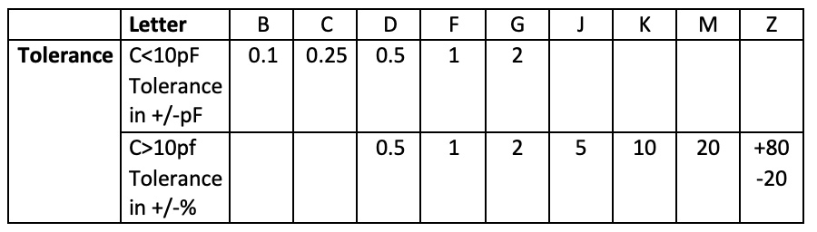
For example, if 47F is printed on a capacitor, it means that its value of capacitance is 47 pF, and its tolerance is one percent. Similarly, if 472J is printed on a capacitor, it means that its value of capacitance is 4700 pF or 4.7nF, and its tolerance is five percent. The letter codes for commonly available capacitances are listed in the following table:
 The ceramic capacitors have additional codes, consisting of a digit between two letters, to indicate temperature range and temperature coefficient. The letters and digits in these codes have the following indications:

The voltage rating is indicated by a number that expresses the working voltage in Volts. Like, the number ’50’ indicates an operating voltage of 50V.
In the next article, we will discuss supercapacitors.
You may also like:


Filed Under: Tutorials

Questions related to this article?
👉Ask and discuss on EDAboard.com and Electro-Tech-Online.com forums.
Tell Us What You Think!!
You must be logged in to post a comment.