In the previous tutorials, we discussed setting up an electronics lab and learned rudimentary know-how of resistors. Moving on with a discussion on passive components, let’s talk about the capacitor.
Let us begin with a fictitious circuit
Imagine a purely resistive circuit driven by an ideal voltage source or ideal current source. In such a fictitious ideal circuit, purely resistive components (of purely resistive load circuit) have fixed voltage drops across them in no time. Once the circuit is powered, the voltage drops across the components become constant and constant currents flow through them all the time.
Let’s get back to reality
Practically, no electronic or electrical circuit behaves like our fictitious circuit. There are no purely resistive components (even resistors show some reactance), ideal voltage sources, or ideal current sources. Even if a resistive circuit is powered by a constant voltage source or constant current source, it passes through a transient state before reaching a fixed, stable state. So, all circuits and their components on the application of a voltage or current experience voltage or current changes through them. A course may reach a stable state only after some time.
DC circuits & DC signals
Broadly, electrical signals can be classified as DC and AC signals. Any voltage or current source is a two-terminal device that can conduct current in two directions in any circuit. A DC circuit is a circuit in which current flows only in one direction from the voltage or current source driving it. So, DC signals can be defined as electrical signals with a fixed polarity and in which voltage and current change only in one direction. There is no reverse of polarity or change in the direction of current across the source driving the circuit.
Practically, DC is a generalized term. It may also refer to a DC component of an electrical signal or the DC behavior of an electrical or electronic component. A DC signal may have voltage or current varying with time but never involves the reversal of voltage polarity or reversal of direction of the current.
AC circuits & AC signals
A voltage source that supplies voltage in which polarity keeps on reversing alternatively is called an AC voltage source. Similarly, a current source that supplies current in which the direction keeps on alternating is called an AC source. A circuit powered by an AC voltage source or an AC source has a reversal of voltage polarity and trend of current alternatively. Such circuits, where voltage and current keep changing direction periodically, are called AC circuits. An AC signal can be defined as an electrical signal in which voltage polarity and current direction keep alternating periodically. The voltage and current rise to a peak value, drop to zero reversing direction, again rise to a peak value in the opposite direction, and then drop to zero, reversing direction. This continues until the signal remains live.
Signals, DC circuits & AC circuits
The changing magnitude (and direction) of voltage and current are all for the sake of good. If signals do not change with time, they are of no practical use. After all, electronics is all about processing electrical signals. DC circuits process electrical signals in which voltage and/or current changes only in one direction. AC circuits process electrical signals in which voltage and current change in magnitude and keep on changing direction alternatively.
More opposition to current: capacitance & inductance
Similar electronic materials and components show some natural opposition to current flow. This is defined by “resistance.” They also oppose any change in magnitude and direction of the current. This is defined as “inductance”. The inductance comes from an opposing magnetic field induced in electronic materials and components in response to changing or alternating current.
Similarly, electronic materials and components show opposition to current due to opposing electrical fields induced due to retaining or storing of charge carriers by them. This is defined as “capacitance.” The resistance remains present in DC and AC circuits and shows similar signal behavior to DC and AC signals. Only AC or DC circuits with pulsating DC signals show the inductance and capacitance. In DC circuits involving constant DC signals, inductance and capacitance are not much significant (and are also unwanted).
While resistance dissipates electrical energy in the form of heat, inductance and capacitance temporarily store electrical energy in the form of magnetic and electrical fields, respectively, and give it back to the circuit again in the form of electrical power. So, there is no energy loss due to inductance or capacitance, unlike in the case of resistance.
Capacitance
Capacitance is the property of electronic material or components by which it can temporarily store electrical charge. Capacitance is the amount of charge stored by an electronic entity per unit volt of applied potential difference.
C = Q/V
Where,
C = Capacitance (in Farad)
Q = Stored charge (in Coulombs)
V = Applied voltage (in Volts)
Obviously, a component having higher capacitance can store a more significant amount of charge per unit of applied voltage. Not all materials or components can store charge in response to an applied potential difference. Some special insulating materials that can polarize in response to applied potential difference show capacitance. Such electronic materials are called dielectric materials or simply dielectrics. Fortunately, air or vacuum can serve as a dielectric medium, allowing the electric field to set up between two conductors in response to an applied voltage.
The devices designed to store charge in an electrical field in response to the applied potential difference (voltage) are called capacitors. The simplest capacitor can be two metal plates (electrodes) separated by air or vacuum. If the two plates are shorted, they are nothing more than a connecting wire. The presence of air or vacuum, a dielectric medium, between the plates makes this setup capable of storing electric charge with some potential difference (voltage).
So, any capacitor is a setup of two electrodes (conducting materials) separated by a dielectric medium. The unit of capacitance is Farad (Coulomb/Volt), in honor of Michael Faraday. The property of a dielectric medium determining charge stored per unit volume on the application of unit voltage is called its permittivity. The permittivity of free space or vacuum is a constant called absolute permittivity equal to 8.85×10⁻¹² Farad/Metre. The permittivity of a dielectric medium relative to absolute permittivity is called its relative permittivity or dielectric constant. The capacitance of a capacitor depends upon the permittivity of the dielectric medium used in it, the shape, size, and construction of the capacitor.
Unit of capacitance
Farad is too large of a unit for expressing standard capacitance. So, the capacitance of standard capacitors is expressed in sub-multiples of Farad like Microfarad (10-6F), Nanofarad (10-9F), and Picofarad (10-12F).
Signal analysis of capacitors
Let us first see the behavior of a capacitor in a DC circuit. The capacitors are designed to store charge temporarily in a circuit. The most simple DC circuit with a capacitor can be a capacitor connected with a voltage source via a switch. A resistor (remember bleeding resistors) can be connected in parallel to the capacitor via another switch for discharging the capacitor.
Initially, there is no potential difference across the capacitor and let us assume that no charge is initially stored in the capacitor. When the voltage source is connected to the capacitor, a potential difference of equal voltage is applied across the capacitor. In response to an applied voltage, the dielectric medium of the capacitor starts polarizing and begins storing charge in the form of an electric field. The following equation gives the charge that the capacitor can store:
Q = CV
So, the current through the capacitor is given by the following equation:
i = dQ/dt
= d(CV)/dt
= C dV/dt
And the voltage across the capacitor is given by the following equation:
dV = i/C . dt
So, ∫dV = 1/C * ∫i.dt
= 1/C * 0∫t i.dt
Charging of the capacitor
Voltage across the capacitor is proportional to the charge stored by it and inversely proportional to the capacitance of the capacitor. The charge is not stored instantaneously within the capacitor in response to an applied voltage. When voltage is applied across the capacitor, it acts as a short circuit, and maximum current flows through it. The current through the capacitor decreases exponentially with the charge stored by it and voltage across it increasing by the same rate. The current through the capacitor ceases when the voltage across the capacitor rises equal and opposite to the applied voltage. Now, the capacitor acts as an open circuit, and no current flows through it while an equal and opposite voltage has developed across it. So, current flows through the capacitor only until the voltage across it changes. Once the voltage across the capacitor becomes constant (equal and opposite to applied voltage), it has no current flowing through it. The voltage across the capacitor remains even when no current is flowing through it as the rate of change of voltage across the capacitor is proportional to current and inversely proportional to capacitance; the greater the capacitance of a capacitor, the slower the rate of change of voltage (rise of voltage) across it.
Discharging of the capacitor
Once the capacitor has equal and the opposite voltage across it, it is fully charged, retaining a charge equal to CV, and no current flows through it. There will be no change in current or voltage across the capacitor until the applied voltage is changed or varied. So, in a constant DC circuit, the capacitor will get fully charged (exponentially) and eventually become an open circuit. Now, it needs to be discharged either by shorting its terminals or through a bleeding resistor. Either way, a discharging current flows through the capacitor in the opposite direction of the charging current. Like charging current, the discharging current is initially maximum and decreases exponentially. The voltage across the capacitor also decreases exponentially along with the discharging current. The discharging current ceases as the voltage across the capacitor reduces to zero.
The capacitor in the AC circuit
Now, let us assume that the voltage source is AC. As a sinusoidal voltage source, the applied voltage will be given by the following equation:
V = Vm sin(ωt)
Where,
V = voltage of waveform at an instant
Vm = Peak voltage of the waveform
ω = Frequency of the waveform
t = time instant
The following equation will give the current through the capacitor:
i = C dV/dt
= C d(Vm sin(ωt))/dt
= ω C Vm cos(ωt)
= Im cos(ωt) where Im = ω C Vm
= Im sin(ωt + 90°)
The opposition to the current by the capacitor is called Capacitive Reactance. The following equation gives it:
Xc = V/I
= Vm/Im OR Vrms/Irms
= 1/ωC
We can then see that current through an AC circuit’s capacitor leads voltage by 90° or 1/4 of the frequency as the applied voltage rises to peak value, the capacitor charges, and the charging current decreases exponentially from the maximum value to zero while the voltage across the capacitor increases exponentially, rising equal and opposite to the applied voltage. So, at the 90° phase angle of the applied voltage signal (1/4 of the signal frequency), the charging current through the capacitor has reduced to zero (from maximum), and the voltage across the capacitor has raised from zero to peak voltage.
As the applied voltage drops from peak value to zero, a current in the reverse direction flows through the capacitor, which rises from zero to a maximum value. The voltage across the capacitor drops along with the applied voltage, reducing to zero and discharging the capacitor. Therefore, at a 180° phase angle of the applied voltage signal (1/2 of the signal frequency), the discharging current (here, current in the reverse direction due to decreasing applied voltage) flows in the opposite direction, rising from zero to maximum value and voltage across the capacitor drops from peak value to zero.
Now, the applied voltage signal reverses the polarity, and the applied voltage rises from zero to peak value in the opposite direction. This again starts charging the capacitor, increasing the voltage across the capacitor equal and opposite to peak voltage (in the reverse direction) and reducing the current through the capacitor from peak value to zero. So, at a 270° phase angle of the applied voltage signal (3/4 of the signal frequency), the voltage across the capacitor has raised to a peak value with opposite polarity, and current through the capacitor flowing in the opposite direction drops to zero from peak value (in the reverse direction).
As the applied voltage drops from peak value to zero in reverse polarity, a current flows through the capacitor in a positive direction rising from zero to a peak value, and the voltage across the capacitor (in reverse polarity) drops from peak value to zero. This discharges the capacitor. So, at a 360° phase angle of the applied voltage signal (completion of one cycle of AC signal), the voltage across the capacitor has again dropped to zero, discharging the capacitor, and the current through the capacitor has again raised to the peak value in a positive direction. The AC response of a capacitor can be illustrated through the following signal diagram:
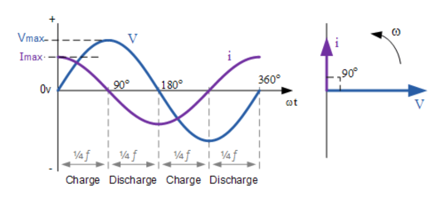
Graph showing voltage and current through a capacitor in an AC circuit (Image: Electronics-Tutorials).
The signal behavior of a capacitor can be summarized as follows:
1) A capacitor is meant to temporarily store charge in a circuit, which returns to the circuit on discharging. The stored charge is returned as a discharging current in the opposite direction of the charging current.
2) Whenever the applied voltage to a capacitor in any direction increases, the capacitor charges. The current through it decreases exponentially, and the voltage across it rises exponentially until it equals the applied voltage. When charging, the voltage across the capacitor develops opposite to the applied voltage and current, always in the direction of applied voltage (and opposite to voltage developed across the capacitor).
3) Whenever the applied voltage to a capacitor in any direction decreases, the capacitor discharges. The current through it increases exponentially, and the voltage across it decreases exponentially until the capacitor is fully discharged or discharged to the lowest level depending upon the fall in the applied signal. When discharging, the voltage through the capacitor develops along the direction of the initially applied voltage. The current is always in the opposite direction to initially applied voltage (charging voltage).
4) The current flows through the capacitor until the voltage applied to it changes. Increasing voltage charges the capacitor, and decreasing voltage discharges the capacitor. The voltage across the capacitor remains even if no current flows through it until discharged due to a decrease in applied voltage, or discharged through a resistor (or load), or by shorting.
5) In an AC circuit or response to an AC signal, the current through the capacitor always leads voltage across it by 90°. The current through the capacitor depends upon not only capacitance and the rate of change of voltage but also the frequency of the applied signal.
6) The opposition to current by a capacitor (capacitive reactance) is inversely proportional to its capacitance and the applied voltage frequency. The higher the capacitance of a capacitor, the less its capacitive reactance. Similarly, the higher the frequency of the applied voltage signal, its capacitive reactance is less. The capacitor acts as an open circuit for a constant DC signal after charging to a peak level. So, a capacitor can be used to block DC signals or DC components of electrical signals. Similarly, due to the frequency dependence of capacitive reactance, capacitors can be used to filter AC signal frequencies.
7) Since capacitors temporarily store charge, they are used in electrical memories.
In the next article, we will discuss different types of capacitors and their applications.
You may also like:

Filed Under: Featured Contributions

Questions related to this article?
👉Ask and discuss on EDAboard.com and Electro-Tech-Online.com forums.
Tell Us What You Think!!
You must be logged in to post a comment.