We have already discussed fixed resistors and variable resistors. Interestingly, resistors are not just limited to be used for limiting current, dropping voltage and dissipating power. There are many special types of resistors which work as transducers too and so, they can be used as sensors in the circuits. A transducer is a device which converts variations in a physical quantity to electrical signals or vice-versa. Some special type of resistors have their resistance dependant on a physical quantity like incident light, pressure, temperature, voltage or magnetic field. This dependence of their resistance on a physical quantity helps in measuring the particular physical quantity or designing related sensor.
So, dependent resistors are variable resistors whose resistance changes relative to a physical quantity. There are mainly the following types of dependent resistors:
1) Light Dependent Resistors
2) Voltage Dependent Resistors
3) Thermistors
4) Magnetic Dependent Resistors
5) Strain Gauges
Light Dependent Resistors
The resistance of Light Dependent Resistors (LDR) changes with respect to the incident light. Their resistance decreases as the intensity of incident light increases and vice-versa. Due to this property, these resistors can be calibrated to identify dark or light situations. In dark, LDR generally offers resistance as high as 1 Mega Ohm, while in light their resistance drops to few hundred ohms or few ohms. This large variation in resistance results into a significant change in the voltage drop across the LDR, which can be used in a voltage division configuration to identify dark verses light situation.
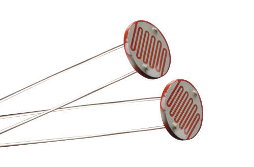
Example of a Light Dependent Resistor (Image: Indiamart)
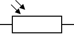
LDRs are also called Photoresistors. These resistors are made up of high resistance semiconductors which are capable of absorbing photons. Depending upon the intensity and frequency of incident light, bound electrons in the semiconductor jump into the conduction band, therefore decreasing the resistance. The change in resistance of LDR is dependent on the frequency (or wavelength) of the incident light. The semiconductors commonly used to make photoresistors include cadmium sulfide, cadmium selenide, lead sulfide, lead selenide, and indium antimonide. Though, several countries have now banned photoresistors made from cadmium or lead as these photoresistors are not compliant to RoHS standards and may be harmful to the environment. The photoresistors have the following IEC standard symbol:
Types of LDR
There are two types of photoresistors (LDRs):
1) Intrinsic Photoresistors – These photoresistors are constructed by un-doped semiconductors like Silicon and Germanium. These LDRs generally have low sensitivity.
2) Extrinsic Photoresistors – These photoresistors are constructed by doped semiconductors. Due to doping, these LDR show a sharp decrease in resistance on exposure to light. So, these photoresistors have good sensitivity.
Performance Indicators of LDR
The intended function of any LDR is its ability to detect light verses dark situation. Therefore, the performance indicators of LDR are properties like sensitivity to intensity of light, wavelength dependency and latency. These KPIs are described below.
Sensitivity – Ideally, the resistance of LDR should decrease with the increase in the intensity of incident light. For constant light intensity, its resistance too must remain constant. Practically, the resistance of LDR changes non-linearly relative to the intensity of light. Also, for constant light intensity, the resistance may still fall due to temperature changes. So, it is important to note the Maximum Power Dissipation of the LDR for a given temperature range. The thermal effect in LDR is often indicated by Maximum Resistance and Minimum Resistance for same light intensity. Other important specifications useful in anticipating the sensitivity of LDR include Typical Resistance and Dark Resistance of the LDR.
Wavelength Dependence – All semiconductors have unique spectral response curves so LDRs have different sensitivity to different wavelengths. The LDRs are generally designed to have a sensitivity to light wavelengths visible to humans. So, their sensitivity remains quite inclined to the infrared range of the light spectrum. The wavelength or frequency dependence of photoresistors is usually indicated by Wavelength Verses Sensitivity Curve and Peak Wavelength of LDR.
Latency – The change in resistance of photoresistors on exposure or blocking of light is not sudden. The photoresistors usually take one second to raise resistance in dark situation while they take approximately 10 ms to drop resistance on illumination. The time required by LDR in dropping or rising its resistance relative to incident light is called latency. The latency of LDR may be indicated by Dark Resistance at different time instants in a dark situation.
LDR versus photodiodes and phototransistors
Due to latency and variation in resistance due to thermal effects, LDRs are not the best light sensor. Now, most of the electronic circuits use photodiodes or phototransistors for light-sensitive applications. The photodiodes and phototransistors are active components and have true PN junctions. This gives them sharp sensitivity to the light and as being active components, these have very low latency. The LDRs are still used in some circuits where only light or dark situation has to be detected without precision. The LDR is also used in audio compressor circuits where the latency of the LDR proves useful in smoothing audio signals.
Voltage dependent resistors
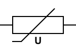
Voltage dependent Resistors, also known as Varistors are variable resistors whose resistance changes relative to the applied voltage. These resistors show a sharp drop in resistance when the applied voltage exceeds a threshold voltage level. This property of varistors make them useful in overvoltage protection circuits and surge protection applications. These resistors come in a variety of packages like axial, radial, disc and block. For high power applications, block type VDRs are used. The varistors have the following IEC standard symbol:
Types of VDR
There are mainly two types of VDR:
1) Metal Oxide Varistor (MOV) – This is the most commonly used varistor. It is made of a sintered matrix of zinc oxide grains which act as a matrix of series and parallel connected diodes.
2) Silicon Carbide Varistors – Theses varistors are suitable for high power and high voltage applications. These are made up of a sintered matrix of silicon carbide. A major drawback of these varistors is their standby current which leads to large power dissipation.
Performance indicators of varistors
The important KPIs of varistors include clamping voltage, maximum pulse energy, maximum rated AC/DC voltage, peak current and standby current. The voltage-current characteristics of a varistor are similar to a diode. It conducts very small leakage current until the voltage reaches clamping level. Beyond clamping voltage, there is a sharp drop in resistance and a large avalanche current flows throw the varistor. The change in current is non-linear with respect to the applied voltage. It is important to note that repeated exposure to voltage surges lower the clamping voltage of varistors. This may result in a short circuit and may lead to a fire hazard. So, a varistor of high clamping voltage must be used in any application and a thermal fuse must be connected in series with it.
Thermistors
The resistance of all resistors whether fixed or variable has some dependency on the temperature. This is indicated by the temperature coefficient of the resistors. The temperature coefficient can be either positive or negative. For fixed or variable resistors, the temperature coefficient must be minimum. So, the fixed or variable resistors are constructed to have a minimum temperature coefficient with as much possible operating temperature range. The dependence of resistance on temperature is sometimes required in applications like sensing temperature, heat regulation, over current protection, etc. The resistors that are designed to have a significant change in resistance relative to the change in temperature are called Thermistors or Thermal Resistors.
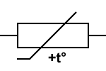
The Thermistors are temperature sensitive resistors which can be used as temperature sensors. These are designed to have high-temperature coefficient. Mostly, thermal resistors have a negative temperature coefficient. These are called NTC Thermistors. The thermal resistors having positive temperature coefficient are called PTC Thermistors. Thermistors are constructed from ceramic semiconductors (metal oxides) and special additives mixed to achieve high-temperature coefficient. Thermistors come in a variety of packages like radial, axial, glass, probe, threaded, etc. The radial package is the most commonly used package type for thermal resistors. The thermistors have the following IEC standard symbol:
NTC thermistors
NTC thermistors are thermal resistors having a negative temperature coefficient. Their resistance decreases significantly with the rise in temperature. These resistors are constructed from ceramics or polymers like nickel, cobalt, manganese, platinum, iron, titanium, etc. These resistors are generally used as temperature sensors. Compared to other temperature-sensing devices such s Resistance Temperature Detectors (RTDs) and Silicon Temperature Sensors (Silistors), NTC thermistors have typically five to ten times greater temperature coefficient. However, non-linearity of their temperature dependence makes using NTC thermistors a tricky thing.
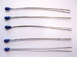
Example of NTC Thermistor (Image: Amphenol Advanced Sensors)
These thermistors are used for applications like temperature sensing, temperature control, temperature compensation, current limiting, time delay, surge suppression, and flow measurement. The applications like temperature sensing, temperature control, and temperature compensation utilize dependence of thermistor resistance on temperature. In such applications, NTC Thermistors are connected to pass minimum current through them and temperature is estimated by measurement of the voltage drop across it. The applications like current limiting, surge protection, time delay, and flow measurement are based on heat capacity and dissipation constant of thermal resistors. In such applications, thermistors are connected in such a way that they start conducting large current once beyond their dissipation constant, which triggers or bias some other component in the circuit.
Performance indicators of NTC thermistors
The NTC Thermistors have the following important properties:
Operating Temperature Range – Most of the NTC Thermistors (which come available in bead, disc or chip packages) have an operating temperature range between -55°C and 200°C. There are special thermistors (which come available in glass encapsulated packages) that have operating temperature range beyond 150°C or as low as absolute zero temperature.
Temperature Sensitivity – Thermistors typically have non-linear resistance curve. Their temperature sensitivity is indicated by a resistance-temperature characteristic curve and percentage change in resistance per degree Celsius. Thermistors typically have -3%/°C to -6%/°C temperature sensitivity. Though thermistors have a low-temperature range (-55°C to 200°C) compared to RTD (-200°C to 800°C), these have higher temperature sensitivity and so the response speed with resistance changes sharply relative to the temperature. The rate of change of resistance of thermistor is expressed as gradient of its resistance-temperature characteristic curve, which is called B-Constant of the Thermistor.
Heat Capacity – Heat capacity is the amount of heat required to raise the temperature of thermistor by 1°C. It is expressed in mJ/°C. Heat Capacity is an important characteristic that must be considered in applications like temperature control, temperature compensation, and inrush current limiting.
It must be noted that due to the non-linear characteristic curve of NTC thermistors, it might not be possible to get accurate and precise results of it in analog circuits. NTC Thermistors are best used with digital circuits that can be programmed to compare a look-up table based on a characteristic curve of the thermistor with analog voltages converted to digital values through ADC.
PTC thermistors
PTC Thermistors are specially designed thermistors that have a positive temperature coefficient. Their resistance increases with the rise in temperature. PTC Thermistors come in two types – Linear PTC Thermistors and Switching Type PTC Thermistors. The linear PTC Thermistors are constructed from Silicon and have a linear resistance-temperature characteristic curve. These are also called Silistors. These PTC Thermistors are used for temperature sensing and measurement.
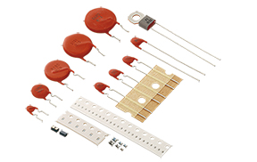
Example of PTC Thermistors (Image: Murata)
The Switching Type PTC Thermistors have a non-linear resistance-temperature characteristic curve and are designed such that they exhibit a sudden change in resistance at a pre-defined temperature called Switch or Transition Temperature. These type of thermistors are constructed from plastics like barium carbonate, titanium oxide, lead titanate, etc and additives like silica, tantalum, and manganese. These Thermistors are used for applications like over-current protection, time delay, motor control, liquid level indicators, and heat regulators.
Performance indicators of PTC thermistors
The PTC Thermistors have the following important properties:
Operating Temperature Range – The operating temperature range of switching type PTC thermistors is typically 60°C to 120°C. Special Switching PTC Thermistors have operating temperature range as low as 0°C and as high as 200°C.
Temperature Sensitivity – The temperature sensitivity of PTC Thermistors is also indicated by the resistance-temperature characteristic curve and percentage change in resistance per degree Celsius. The Silistors typically have temperature sensitivity of 0.7%/°C to 0.8%/°C. The silistors have a linear resistance-temperature characteristic curve while the resistance of switching type PTC thermistors initially decreases with rise in temperature and beyond a particular temperature, their resistance increases significantly with every degree rise in temperature. This temperature is called transition temperature.
Transition Temperature – The Transition or Switch Temperature is the temperature at which the temperature coefficient of switching type PTC Thermistor turns from negative to positive and resistance starts changing rapidly relative to the rise in temperature.
Minimum Resistance – This is the resistance of switching type PTC thermistor at the transition temperature. This is the minimum resistance offered by the PTC Thermistor.
Rated Resistance – This is the resistance of PTC thermistor at 25°C.
Dissipation Constant – The dissipation constant of PTC thermistor relates applied electrical power with the rise in temperature of the thermistor. It is a constant that is dependent on the material, shape, size, ambient temperature and construction of the PTC Thermistor.
Maximum Rated Voltage – This is the maximum voltage that can be tolerated by the PTC Thermistor.
Maximum Rated Current – This is the maximum current that the PTC thermistor can withstand.
Magnetic Dependent Resistor
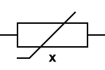
Magnetic Dependent Resistor or Magneto Resistor is a variable resistor of which resistance varies relative to the strength of an applied magnetic field. These resistors can detect the presence of the magnetic field, its polarity, and strength. These resistors are based on anisotropic magnetoresistance (AMR) effect. These resistors are constructed from ferromagnetic materials. Typical MDR resistor consists of four perm-alloy films connected like a Wheatstone bridge. These resistors are used in the detection of the magnetic field, measurement of magnetic strength and polarity, electronic compass and position sensors. The MDR has the following IEC standard symbol:
Strain gauge
Strain gauges are variable resistors where the resistance varies relative to the applied force. These resistors are made up of a metallic foil enclosed in an insulating case where deformation in foil varies the resistance. These resistors are used for the measurement of pressure, force, weight, and tension. The variation in resistance of strain gauge is indicated by gauge factor. Gauge factor is defined as a ratio of relative change in resistance of strain gauge to the mechanical strain.
In the next article, we will discuss power resistors. Before that here are three Do-It-Yourself Activities for you.
Activity 7
Download some random datasheets of LDR, Photodiodes, and Photo-transistors. Compare their sensitivity and latency.
Activity 8
Look for any microcontroller circuit using NTC Thermistor for sensing temperature. Check out how microcontroller is programmed to calibrate sensor measurements relative to the resistance-temperature curve of the Thermistor.
Activity 9
Explore some random datasheets of switching type PTC Thermistors. Observe their transition temperature and resistance-temperature characteristic curves.
Filed Under: Featured Contributions



Questions related to this article?
👉Ask and discuss on EDAboard.com and Electro-Tech-Online.com forums.
Tell Us What You Think!!
You must be logged in to post a comment.