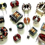
We have already learned about working with, types of, and applications of inductors. In the previous article, we have previously discussed selecting an inductor for a given circuit or application. When choosing the right inductor, it is important to know about reading inductor packages. There are many types of inductors that come in a variety of sizes. The inductors of large size often have important technical specifications printed on the package. The inductors of moderate to small size generally use numerical or color codes for an indication of their technical specifications.
Most of the inductors have their nominal inductance in Micro-Henry or Milli-Henry range. Apart from inductance value, tolerance is another important specification that is marked on most of the inductor packages. For other specifications, engineers need to consult the datasheets supplied by the particular vender. The inductor packages have the following numerical and color-coding systems for an indication of nominal value and tolerance –
Numeric coding
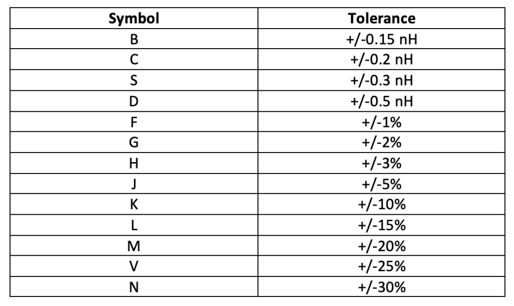
This is the most common type of coding system used by manufacturers. In this system, the value of the inductor is printed as an alphanumeric code consisting of digits and alphabets. It is a three- or four-letter code which indicates inductance in Micro-Henry. The first two digits indicate the significant digits of the inductance value, and the third digit indicates the multiplier. The fourth letter is always an alphabet to indicate tolerance according to the following table:
4-band color coding
For example, If an inductor has a numerical code of 102K printed on it, it implies that it has an inductance of 1000 Micro-Henry or 1 Milli-Henry with a tolerance of 10 percent.
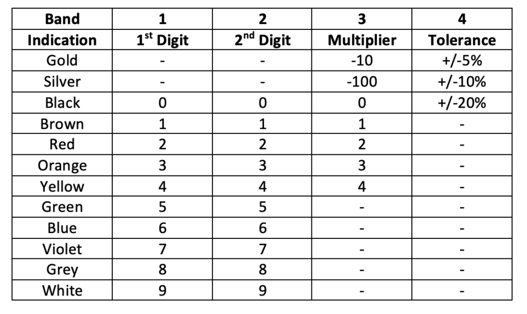
Another popular method used by manufacturers for an indication of nominal value and tolerance is color-coding. This type of coding system is preferred for inductors that come in axial or radial packages like molded inductors. There can be 4-band or 5-band color coding. The color bands are printed near one end of the inductor from where the bands are read sequentially. In 4-band color codes, the first two bands indicate the significant digits of the inductance value, and the third band indicates the multiplier. The value of inductance is in Micro-Henry. The fourth band indicates the tolerance. The following table can decode a 4-band code:
5-band color coding
For example, if an inductor has a color-coding with the first band yellow, the second band violet, the third band brown, and the fourth band black, then the inductor has a nominal value of 470 uH and a tolerance of 20 percent.
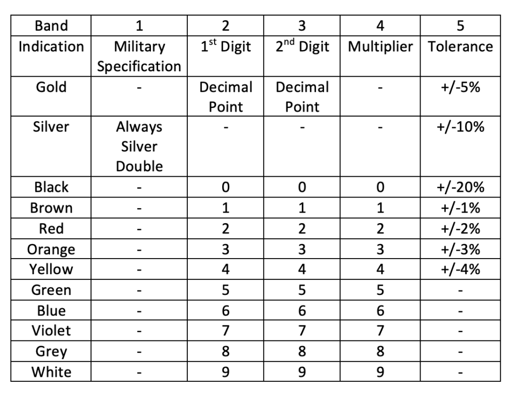
The 5-band color coding is used on radial molded inductors that are used as military radio frequency inductors. In these inductors, the first band is always silver, which indicates that the inductor is for use in military-grade applications. The second and third band indicates the significant digits of the inductance value, and the fourth band indicates the multiplier. The value of inductance is in Micro-Henry. The fifth band indicates the tolerance. These inductors can have tolerance as low as 1 percent. The following table can decode a 5-band code:
For example, if a molded inductor has a 5-band color code printed on it such as the first is a double silver band, the second band is blue, the third band is green, the fourth band is brown, and fifth band is red, then it is a military radio frequency inductor having a nominal inductance of 650 Micro-Henry with tolerance of 2 percent.
Surface mount inductor codes
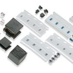
Surface mount inductors or chip inductors use color dots instead of color bands. There are generally three dots that are read clockwise from the top. The first two dots indicate the significant digits of the inductance value, and the third dot indicates the multiplier. The value of inductance is obtained in Nano Henry. The inductor value is decoded according to the color-coding of the 4-band system. If there is a single dot on a chip inductor, it implies that its datasheet should determine the value and tolerance of the inductor.
RF inductors color codes
RF Inductors also have their value of inductance indicated by dots. These inductors are similar to SMD inductors but are smaller in size. If there is a single dot on RF inductor, it implies that the value of inductance and tolerance can be determined by the inductor’s datasheet. If there are three dots, two dots lie on one end, and one dot is printed on the other end. The two dots are read from top to bottom and indicate significant digits of the inductance value. The single dot on the other end indicates the multiplier. The value of inductance is obtained in Nano Henry. The color-coding follows the coding scheme of the 4-band system.
So, now you can read inductance and tolerance of any inductor available in any package. Just derive the value of required inductance and tolerance, and pick up the right inductor. Check out other specifications from the datasheets provided by the manufacturer or vendor if required. In the next article, we will discuss transformers.
You may also like:
Filed Under: Tutorials




Questions related to this article?
👉Ask and discuss on EDAboard.com and Electro-Tech-Online.com forums.
Tell Us What You Think!!
You must be logged in to post a comment.