In the previous article, we presented a resistor selection reference table. With the help of this table, you can determine which type of resistor will be most suitable for a given circuit or application. Once you’ve determined which type of resistor suits the best, it’s time to pick up the desired resistor. For that, it is essential to identify value, tolerance, and power rating of the resistor.
The value and tolerance of carbon composition, ceramic composition, carbon film, metal film, and metal oxide film resistors are identified by the color codes. Labels identify the value and tolerance of cermet, wirewound, and foil resistors. The power rating of all types of resistors is determined by measuring or observing their physical size. Even before identifying value, tolerance, and power rating of a resistor, it is important to check out if the exact value of the desired resistance is available or not. There are standard values of resistances available for different types of resistors. If the precise value of required resistance is available, then that can be picked up without question. Otherwise, suitable parallel or series combination of resistors need to be figured out.
Standard values of resistors
Resistors come available in standard values or preferred values. These standard values are a recommendation of the International Electrotechnical Commission (IEC) and were first published in standard IEC 60063 in the year 1952. These preferred values are called E-series. These standard values are also applicable to other components like capacitors, inductors, and Zener diodes.
The standardization of resistor values was not only good for electronics engineers, but it was also equally useful for the manufacturers. It was challenging to figure out the manufacturer of resistors as resistors are quite small to denote name or trademark of its manufacturer. In the absence of preferred values, electronics engineers had to identify the manufacturer of the resistor then identify the value of the resistors with the help of datasheets provided by the particular manufacturer. The standardization of the resistor values made it possible to develop color codes and numerical codes for the value and tolerance of the resistors. So, after the adoption of E-series by almost all manufacturers around the world, electronics engineers simply need to decode color-coding or numerical codes printed on the resistors to identify their value and tolerance.
On the other hand, the preferred values or E-series helped manufacturers produce resistors with values that equally space on a logarithmic scale. This limited the different values of resistors that need to be produced and stored. The standardization also helped in maintaining compatibility between resistors produced by different manufacturers. Apart from IEC’s E-series, there are various national standards (like ANSI in the USA) which are generally compatible with the IEC standard.
E-Series
E-Series are preferred values for resistors, capacitors, inductors, and Zener diodes. There were 8 E-series – E1, E3, E6, E12, E24, E48, E96 and E192of which E1 is now obsolete. Each E-series divides the interval of 1 to 10 by the number followed after the letter ‘E’ and rounds off the nominal value to either two or three significant digits. For example, E6-series divides each decade (resistances 1Ω to 10Ω, 10Ω to 100Ω, etc.) into six values as follows:
10(1/6) = 1.5
So, each standard value in E6 is 50% higher than the previous value rounded to two significant digits in case of E-6 Series. Therefore, for 1Ω to 10Ω interval, there are six preferred values in E6 series as follow – 1, 1.5, 2.2, and so on.
By such division, the maximum error in the nominal value of the resistor for E1, E3, E6, E12, E24, E48, E96 and E192 series is divided as 50%, 40%, 20%, 10%, 5%, 2%, 1% and 0.5% respectively. The E-192 series is also used for tolerances 0.25% and 0.1% and below. The E1 series is now obsolete, and even E3 series is rarely used anywhere as manufacturers now produce resistors with maximum 20% tolerance or less. So each E-series is associated with tolerance of the resistors as follows:
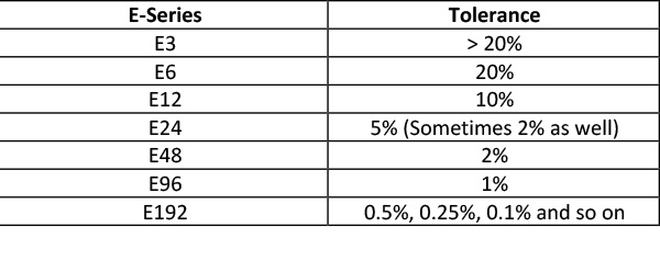
The resistors with tolerance as low as 0.005 are available. Their value is indicated under E192 – Series. The E-series is divided into two groups – one from E3 to E24 and other E48 to E192. The E-series group of E3 to E24 has two significant digits in the resistance value, while the E-series group of E48 to E-198 has three significant digits in the resistance value. The E-series – E6 to E192 are most commonly used. These have the following preferred values of resistances:
E6 Series – E6 Series is used for resistors having 20% tolerance. It has six preferred values, each of two significant digits, for each decade as follows:
10 15 22 33 47 68
E12 Series – E12 Series is used for resistors having 10% tolerance. It has twelve preferred values, each of two significant digits, for each decade as follows:
10 12 15 18 22 27
33 39 47 56 68 82
E24 Series – E24 Series is used for resistors having 5% tolerance. It has twenty-four preferred values, each of two significant digits, for each decade as follows:
10 11 12 13 15 16
18 20 22 24 27 30
33 36 39 43 47 51
56 62 68 75 82 91
E48 Series – E48 Series is used for resistors having 2% tolerance. It has 48 preferred values, each of three significant digits, for each decade as follow –
100 105 110 115 121 127
133 140 147 154 162 169
178 187 196 205 215 226
237 249 261 274 287 301
316 332 348 365 383 402
422 442 464 487 511 536
562 590 619 649 681 715
750 787 825 866 909 953
E96 Series – E96 Series is used for resistors having 1% tolerance. It has ninety six preferred values, each of three significant digits, for each decade as follow –
100 102 105 107 110 113
115 118 121 124 127 130
133 137 140 143 147 150
154 158 162 165 169 174
178 182 187 191 196 200
205 210 215 221 226 232
237 243 249 255 261 267
274 280 287 294 301 309
316 324 332 340 348 357
365 374 383 392 402 412
422 432 442 453 464 475
487 499 511 523 536 549
562 576 590 604 619 634
649 665 681 698 715 732
750 768 787 806 825 845
866 887 909 931 953 976
E192 Series – E192 Series is used for resistors having 0.5% tolerance. It has one hundred and ninety two preferred values, each of three significant digits, for each decade as follow –
100 101 102 104 105 106
107 109 110 111 113 114
115 117 118 120 121 123
124 126 127 129 130 132
133 135 137 138 140 142
143 145 147 149 150 152
154 156 158 160 162 164
165 167 169 172 174 176
178 180 182 184 187 189
191 193 196 198 200 203
205 208 210 213 215 218
221 223 226 229 232 234
237 240 243 246 249 252
255 258 261 264 267 271
274 277 280 284 287 291
294 298 301 305 309 312
316 320 324 328 332 336
340 344 348 352 357 361
365 370 374 379 383 388
392 397 402 407 412 417
422 427 432 437 442 448
453 459 464 470 475 481
487 493 499 505 511 517
523 530 536 542 549 556
562 569 576 583 590 597
604 612 619 626 634 642
649 657 665 673 681 690
698 706 715 723 732 741
750 759 768 777 787 796
806 816 825 835 845 856
866 876 887 898 909 920
931 942 953 965 976 988
Determining if the exact value of desired resistance is available
The standard resistances come available in multiples of 10 with the values as mentioned above. Like, under E6-series, the following resistances come available –
1.0 1.5 2.2 3.3 4.7 6.8 (Multiplier 100)
10 15 22 33 47 68 (Multiplier 101)
100 150 220 330 470 680 (Multiplier 102) and So on.
So, now you can quickly determine if the desired value of resistance is exactly available by matching its two or three significant digits with the preferred values of E-series.
Series and parallel combination of resistances
Often, the exact value of the desired resistance is not available. In such case, two or more resistors can be connected in series, parallel, or combination of series and parallel resistances to get an equivalent resistance. In series combination, the equivalent resistance is simply the sum of the connected resistances as follows:
Req = R1 + R2 +….
In parallel combination, the equivalent resistance is given by shunt formulae as follows:
1/Req = 1/R1 + 1/R2 +….
In a series combination of resistances, the voltage drop is divided among the resistors. Therefore, care must be taken when connecting an equivalent resistance by a series of combination of resistors, as there may be an unintentional voltage division network added to the circuit by false connections to the junctions of the connected resistors. Similarly, it is important to take care of a parallel combination of resistors branch current.
Resistor packages
The resistors generally come in three types of termination – Plated Through Hole (PTH), Surface Mount Technology/Device (SMT/SMD) and Metal Electrode Leadless Face (MELF). The PTH is for use on breadboards, prototyping and through-hole mounting on PCBs. The SMT/SMD termination types are meant for soldering over landing pads on PCBs. The MELF style resistors are like SMD/SMT resistors, but they have a cylindrical shape and no leads. They are also meant to be soldered on landing pads on PCBs. MELF resistors have the advantage of lower thermal coefficient and better stability over SMD/SMT resistors while they may be difficult to handle by a mechanized assembly machine. In all the termination types, resistors come in several shapes and sizes. These shapes and sizes are called packages. The most common is the axial package or radial package with PTH termination. The MELF resistors mainly come in three packages – MicroMELF, MiniMELF, and MELF. Similarly, SMD/SMT resistors come in several packages that are standardized through four-digit imperial or metric codes by organizations like JEDEC.
Color codes for resistors
The standard 2-digit and 3-digit preferred values (E-Series) for resistors make it possible to develop color codes and numerical codes for the resistors. The resistors with PTH or MELF termination have their value and tolerance indicated by color codes. The carbon composition, ceramic composition, carbon film, metal film and metal oxide film resistors are generally available in PTH or MELF termination as axial or radial packages. There are 3, 4, 5, and 6-band color codes for the resistors. Reading these color codes has been explained in the following article .3, 4, 5, and 6-band Resistor Color Codes.
Numerical codes for resistors
The resistors with SMD/SMT termination have their value and tolerance indicated by numerical codes. The SMD/SMT resistors are so small that it is not possible to use color codes on them. So, there are two numerical code systems – three-digit and four-digit numerical code system and EIA-96 system to indicate their value and tolerance.
Three and Four-Digit Numerical Code System
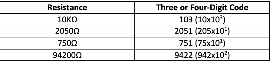
In this system, the value of the resistor is indicated by a three or four-digit number. In the three-digit number, the first two digits indicate the significant digits of the value of the resistor, and the third digit indicates the multiplier. In the four-digit number, the first three digits indicate the significant digits of the value of the resistor, and the fourth digit indicates the multiplier. The values of resistances involving decimal point are indicated by inserting the letter ‘R’ at the decimal place in three or four-digit code. For example, a resistor having value 0.01Ω will have 0R01 code printed on it. The following table shows some of the examples of three and four-digit codes.
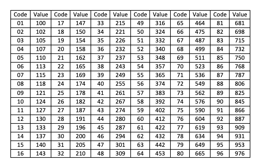
E96 Code System – E96 system is developed to indicate the value of E-96 Series SMD/SMT resistors having 1% tolerance. In E96 code system, the value of the resistor is indicated by three characters of which first two are numbers, and third is a letter. The numbers indicate three significant digits of the resistance value that can be verified through the following look-up table:
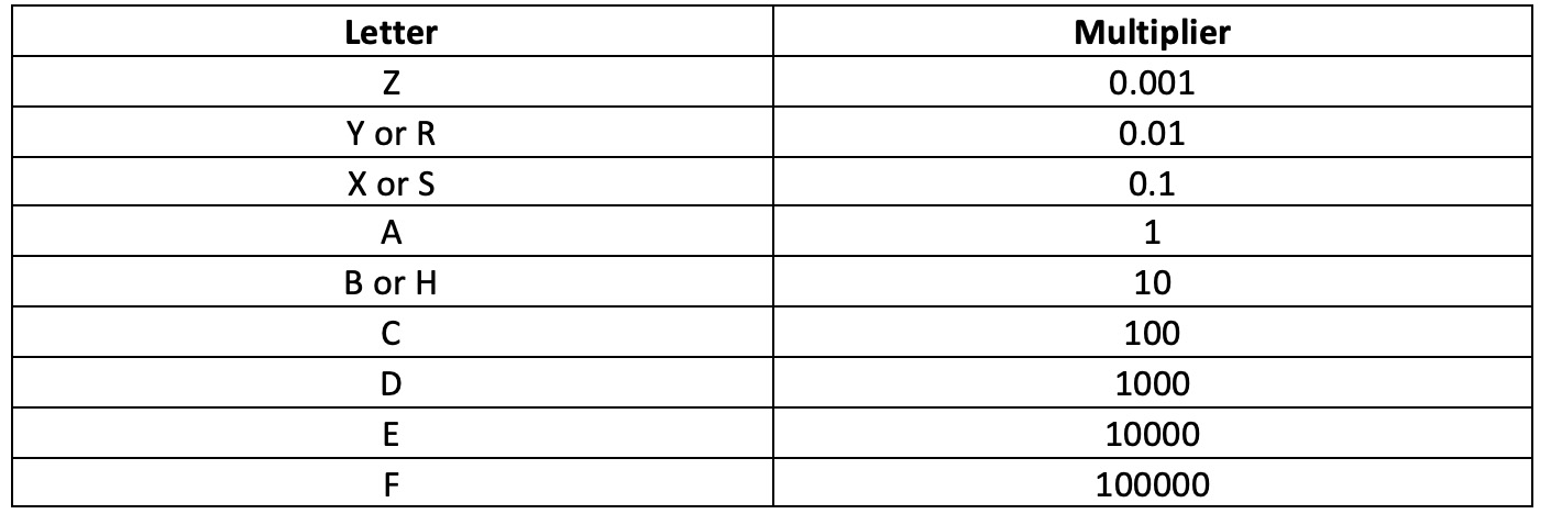
The third character, which is a letter indicates multiplier as per the following look-up table:
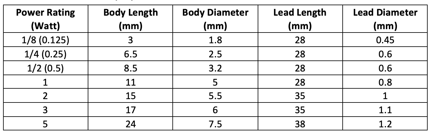
Power rating of PTH resistors
The power rating of PTH type resistors can be determined by measuring or observing their physical size. PTH resistors are generally available in an axial or radial package. Their power rating can be determined by measuring body length, body diameter, lead length, or lead diameter. Obviously, measuring body length will be most convenient and accurate because measuring the diameter of the body or lead of a resistor could be a tough task and the lead length remains the same for several power ratings. Also, leads could be cut short due to different reasons. The following lookup table relates a power rating of PTH resistors with their physical dimensions:
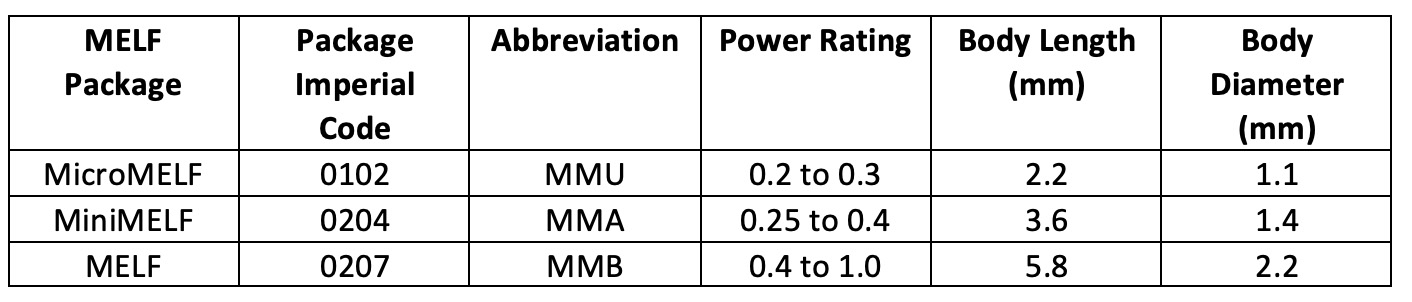
Power rating of MELF resistors
MELF resistors too come in axial or radial packages. The following lookup table relates the power rating of MELF resistors with their physical dimensions:
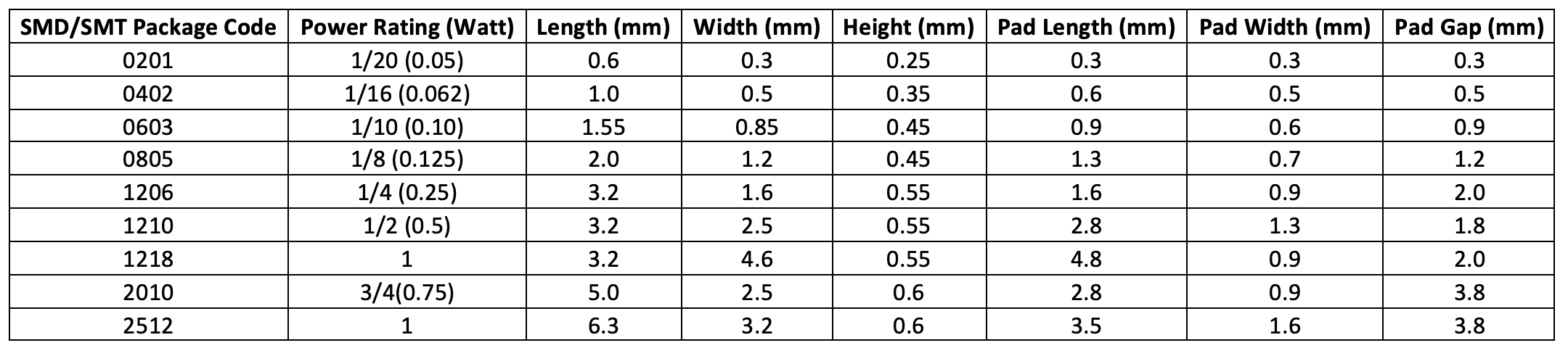
Power rating of SMD/SMT resistors
The power rating of the SMD/SMT resistors can be determined by either measuring their physical dimensions or dimensions of their landing pad on a PCB. The following lookup table relates the power rating of SMD/SMT resistors with their physical dimensions and size of solder landing pad:
Note that some manufacturers particularly of wirewound and foil resistors use their own codes and power rating tables or simply print part numbers. The wirewound resistors usually have wattage printed on them along with their nominal value and tolerance printed or have the part number printed on them. Similarly, manufacturers of foil resistors may have their own coding system according to their national standards. So, in case, there is no color code, numerical code or E96 code printed on a resistor, refer to the datasheet of the particular manufacturer to determine value, tolerance and power rating of the resistor.
Now, you can determine nominal value, tolerance and power rating of any resistor. In the next article, we will discuss variable resistors.
Filed Under: Featured Contributions

Questions related to this article?
👉Ask and discuss on Electro-Tech-Online.com and EDAboard.com forums.
Tell Us What You Think!!
You must be logged in to post a comment.