In the previous article, we discussed the classification of transformers by core material, geometry, and voltage levels. The transformers can also be classified by their application and use. Let’s explore the two broad categories of use cases first – transformers used in the electrical domain and transformers used in the electronics domain.
The transformers used in the electrical domain are classified by their applications as follows:
- Power
- Distribution
- Measurement
In the electronics domain, transformers are classified by the frequency range of their operation as follows:
- Pulse
- Audio
- IF
- RF
Power transformers
Power transformers are used to reduce line voltage in the 60-Hz utility line. These transformers come in a variety of sizes, shapes, and winding ratios. These can be as big as a room and as small as a Rubik’s cube depending upon where they are used which could range from generating plants and high tension power lines to the power portion of electrical appliances. The power transformers are used to convert AC voltages (generally to step down) from the power supply line to electrical circuits or from one part of the power supply line to another. These transformers are usually characterized by the maximum voltage and current capacity of the secondary coil.
The largest of these transformers are used in generating plants. Engineers can do nothing about the energy losses due to wire resistance and power consumed by the loads. So, they are left with the option to transmit high voltage power over the transmission lines. The higher is the voltage, the lower the current so energy losses are minimized over power transmission. The power transformers at generating plants convert high current low voltages to low current high voltage AC. High energy power plants have bigger power transformers that can transfer power as high as 100 MVA over the transmission line. Medium power transformers have a power rating typically from 50 to 100 MVA, while small power transformers used at local power stations have a power rating typically from 500 to 700 KVA.
Power transformers are larger than distribution transformers. These are designed to have maximum power efficiency as these remain loaded 24 hours a day. Such power transformers may be directly connected to the consumer or may connect to a distribution network. Most of the power transformers have a three-phase configuration, while some small power transformers may have a single-phase configuration. The three-phase power transformers are costly, though much power efficient compared to single-phase transformers.
Transformers are used at different points of transmission networks. The high tension lines carry voltages in KV or MV, which cannot be directly supplied to the consumer. The power transformers are deployed to step down these voltages to lower voltages at branch points. The lowered voltages are further stepped down within the network. Finally, the AC voltage is stepped down to three-phase 230V or 120V RMS by distribution transformers to supply at the consumer end.
Small-size power transformers are used in the power section of the electrical appliances to further step down AC mains to low voltages ranging from 5V to 50V. Most of the consumer appliances require 5V to 12V for their operation with minimal current consumption. Different power transformers come in a variety of construction, configuration, and size.
Auto transformers
Auto transformers are power transformers that have primary and secondary on a common coil. Both primary and secondary are on the same coil and have the same direction. The voltage is varied by changing the position of secondary tapping.
Single-phase and three-phase transformers
Power transformers can have a single-phase or three-phase configuration. Single-phase transformers have a single pair of primary and secondary windings. These transformers are generally used in electrical appliances, where they convert voltage levels at a constant frequency.
Three-phase transformers have three pairs of primary and secondary windings connected to each other. These transformers are cost-effective compared to single-phase transformers when used in power generation, transmission, and distribution. The primary and secondary coils in three-phase transformers can have various combinations of star and delta connections like star-star, star-delta, delta-delta, or delta-star connections at primary and secondary windings respectively.
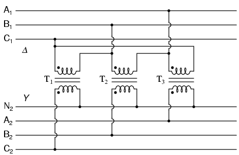
Schematic representation of a typical 3-phase transformer (Image: Quora)
Distribution transformers
Distribution transformers are used in power distribution networks to reduce transmission line voltages to less than 33KV for industrial purposes and 230-440V for domestic purposes. These are generally used at the end of a distribution network as pole-type transformers and can also be pad mount or underground transformers at the distribution end. They are small in size, are not always fully loaded, and may have dry type or liquid immersed insulation. They may be supplying single-phase or three-phase main supply to the consumer end. These transformers are low-cost and designed to have a power efficiency of 50 to 70 percent.
Measurement/instrument transformers
Instrument transformers are used to measure high-value current and voltage and are used along with low-range measuring instruments as accurate ratio transformers. These transformers convert the high voltage or current to low voltage or current by an accurate ratio such that it can be measured by a typical ammeter, voltmeter, or wattmeter. These can be either current transformers that are supposed to be used with an ammeter or potential transformers that are supposed to be used with AC voltmeter.
![Wordtwist [CC BY-SA 3.0 (https://creativecommons.org/licenses/by-sa/3.0)]](https://www.engineersgarage.com/wp-content/uploads/2019/10/Instrument_Transformer-871x1024.jpg)
A 120:120 instrument isolation transformer showing two polarity marking conventions (Image: Wikipedia).
For measuring high-value voltages, the primary of potential transformers or voltage transformers is connected to the supply line, and supply line voltage is stepped down to a safe limit at the secondary. Voltage transformers can be electromagnetic, capacitor, or optical type. Electromagnetic types are simple wire wound step down transformers, capacitor types use a capacitor voltage divider, and optical types use optoelectronic components.
Pulse transformers
Pulse transformers are small-size PCB-mounted transformers used in electronic devices to generate pulses of fixed amplitude. These transformers isolate a digital load circuit and supply pulses of constant amplitude to it.
Audio transformers
It is more appropriate to classify transformers used in the electronics domain by the range of frequency of their operation. The electronic transformers that operate over a frequency range from 20 Hz to 20 kHz are classified as audio transformers. These are generally small-size utility transformers having laminated E-I core similar to typical 60-Hz utility transformers. These can be step-up or step down transformers. Audio transformers are mostly used for impedance matching and are designed to offer almost zero reactance. There can be multiple primary and secondary coils in an audio transformer, which may be separated or center tapped.
IF transformers
IF transformers are used for tuning intermediate frequency signals. These are shielded transformers generally having a ferrite core of high permeability.
RF transformers
The electronic transformers that are used at radio frequencies are called RF transformers. These can be wire-wound transformers like utility transformers or can be transmission line transformers. The wire-wound transformers having a toroidal powdered-iron core are most common. Air-core RF transformers are used for high-power applications. While powdered-iron core transformers have high permeability and self-shielding, air-core transformers are much more energy-efficient, athough they have significant EMI. These transformers are also called broadband transformers and are used for a frequency range from 3 MHz to 30 MHz. At higher frequencies, transmission line transformers as quarter-wave antennas are used. These may be parallel-wire lines or coaxial cables.
Applications of transformers
Transformers are widely used in both electrical and electronics domain. In the electrical domain, transformers are generally used to step down AC voltages at power stations, distribution networks, or for measurement. In electronics, transformers are used for many applications such as step-up or step-down voltages, impedance matching, pulse generation, coupling, and isolation.
Transformers used in the electronics domain generally have their specifications such as the primary voltage, secondary voltage, and power rating printed on them. In general, color schemes identify the leads of the primary coil, secondary winding, and center tap.
Activity 12
That’s enough about transformers. Now, that you are well acquainted with understanding the working and specifications of transformers, it’s time to try out some circuits. Get the circuit diagrams and get your hands dirty with some of the hobby circuits that use transformers like half-wave rectifier, full-wave rectifier, 12V or 9V symmetrical bench power supply, audio power amplifier and pre-amplifier. Inspect the role and required specifications of transformers used in these circuits.
Activity 13
Prepare a list of some pulse generation transformers by their part numbers. Download and inspect their datasheets. Figure out important electrical characteristics mentioned in their datasheets that can be useful in their application.
In the next article, we will discuss power supplies.
You may also like:
Filed Under: Tutorials



Questions related to this article?
👉Ask and discuss on EDAboard.com and Electro-Tech-Online.com forums.
Tell Us What You Think!!
You must be logged in to post a comment.