In the previous article, we learned about the basic concepts of a transformer. A transformer is simply a pair of inductors magnetically coupled to enable electromagnetic induction between them. With the help of transformers, AC voltages can be stepped up or down at low costs without any hassle. Stepping up or down DC voltages requires complex and expensive circuitry. That is why AC is used for the distribution of electric power even though most of the electronic appliances use DC for their operation. The electronic appliances convert the AC mains to DC for their functioning.
Transformers come in a variety of shapes, sizes, and construction. The transformers can be classified by the core material, geometry and construction, voltage levels, and usage.
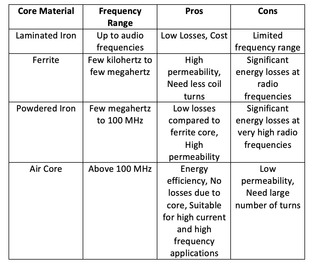
Core classifications are as follows:
- Laminated Iron Core
- Ferrite Core
- Powdered Iron Core
- Air Core
Geometry classifications are as follows:
- Utility
- Solenoidal Core
- Toroidal Core
- Pot Core
Voltage levels classifications are as follows:
- Step-Up
- Step-Down
- Isolation
Usage classifications are as follows:
- Power
- Measurement
- Distribution
- Pulse
- Audio
- IF
- RF
Transformer cores
In the construction of any transformer, the manufacturers try to have maximum magnetic coupling between the two inductors. The magnetic coupling can be increased many folds by using a ferromagnetic material or powdered iron as the core. A pair of inductors wound on a ferromagnetic core have a much better coefficient of coupling compared to the air-core transformer. However, the use of ferromagnetic core has its own limitations. Ferromagnetic cores have some energy losses due to hysteresis and eddy currents and are also limited by current-carrying capacity. Apart from these limitations, the choice of core material also restricts the frequency range of a transformer. According to the type of core used, transformers are classified as follows
Laminated Iron Transformers – These transformers use silicon steel as core material. Silicon steel is also called transformer iron or simply iron. The silicon steel is laminated into layers to avoid losses due to eddy currents and hysteresis. Eddy currents are circular currents that flow in magnetic material on magnetization. The eddy currents lead to loss of energy by the magnetic core in the form of heat. Hysteresis is the tendency of a magnetic core to be slow in accepting fluctuating magnetic flux. Due to losses by hysteresis and eddy currents, these transformers are only suitable for 60 Hz frequency and other low frequencies in the audio range. As the frequency increases above a few kilohertz, internal losses of the core increase beyond feasible limits.
Ferrite Core – Ferrite cores have high permeability and require fewer coil turns. However, at frequencies above a few megahertz, such cores start showing significant energy losses due to eddy current and hysteresis. That is why these transformers are suitable for frequencies above audio frequencies up to a few megahertz.
Powdered Iron Core – Powdered iron also has high permeability and lower losses due to hysteresis and eddy current compared to ferrite cores. As the frequency increases, the need for high permeability decreases. The transformers using powdered iron core are suitable for very high frequencies up to 100 MHz. As there is no need for high permeability at very high frequencies above 100 MHz, air-core transformers are more suitable due to their energy efficiency.
Air Core Transformers – In air-core transformers, both primary and secondary coils are wound on a diamagnetic material. The magnetic coupling in such transformers happens through the air. In such transformers, not only is the inductance of both coils low, but the mutual inductance is also very low so there is very little magnetic coupling between the coils. These transformers have no loss of energy due to hysteresis or eddy currents and are also capable of moderating high currents. Such transformers are suitable for high voltage applications where energy efficiency is a prime concern, such as distribution transformers. These are also suitable for very high RF applications above 100 megahertz. At high radio frequencies, the value of required inductance is low, which can be easily achieved by air-core inductors, and energy efficiency is the primary concern of the VHF circuits.
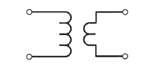
 It should be noted that the following symbol represents air-core transformers:
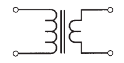
 The transformers having a magnetic core are represented by a symbol in which two parallel lines are added between the coil symbols as follows:
Transformer geometry and construction
Transformers can also be classified by their shape and geometry. The shape of a transformer depends on the type of inductor used in its construction and the shape of its core. Any transformer is essentially a pair of inductors wound on the same core. The classifications are as follows:
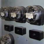
Utility Transformers – Utility transformers are power transformers in which laminated iron is used as the core material. These iron core transformers come with a variety of core shapes like E, L, U, I, etc. and are bulky and heavy. The most common core shape used in these transformers is E core or E-I core because the laminated core has the shape of the letter ‘E’ with a bar placed at the open end of ‘E’ to complete the construction. The coils are wound on the core either by shell method or core method. In the shell method, both coils are wound on the middle bar of the ‘E’ atop each other. This ensures maximum magnetic coupling between the coils, but at the cost of high coil-to-coil capacitance. The shell method also limits the current carrying capacity of the transformer. In the core method, one coil is wound on the top bar of the ‘E’ and the other on the bottom. The magnetic coupling between the coils occurs only due to magnetic flux through the core. The core method reduces the coil-to-coil capacitance to a great extent and makes it possible to handle high voltages. The utility transformers with E-I core having a shell or core winding are most commonly used as 60 Hz transformers and other audio frequency transformers.
Solenoidal Coil Transformers – Solenoidal core transformers are generally used as a loopstick antennas for radio frequency circuits. These transformers have primary and secondary windings on a cylindrical core (ferrite or powdered iron). The coils are either wound atop of each other or separate. In such transformers, the primary captures the radio signals, and the secondary provides impedance matching to the first amplifier stage of the radio circuit. Such transformers have been quite common in portable radio communication equipment.
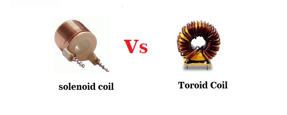
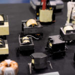
Solenoid coil transformer vs toroidal coil. (Image: Leets Academy)
Toroidal Core Transformers – Toroidal core transformers have a primary and secondary wound on a toroid core and the coils may be wound atop of each other or separate. Toroidal cores are a better alternative of solenoidal cores in radio frequency circuits. They contain the magnetic flux within the core, so that these transformers can be directly mounted without any additional shielding, provided the coils are insulated. Apart from no electromagnetic interference, toroidal cores also provide higher inductance per coil turn. As the magnetic flux remains contained within the core, toroidal core transformers have better magnetic coupling between the coils.
Pot Core Transformers – Pot core transformers have the primary and secondary wound on one of the halves either atop of each other or next to each other. Pot cores provide the highest possible inductance with the obvious advantage of self-shielding. One of the major disadvantages of pot core transformers is coil-to–coil capacitance. Due to coil-to-coil capacitance and unusually high inductance of both coils, pot core transformers are only suitable for low frequencies. At high frequencies, the required value of inductance is low, and capacitive reactance needs to be essentially minimized.
Transformers voltage levels
The most common application of a transformer is to moderate AC voltages. A transformer can step up, step down, or leave intact AC voltage levels. This is the easiest but most important classification of transformers. They are as follows:
Step Up Transformer – In a step-up transformer, the secondary has a higher number of turns than the primary. As the ratio of turns of primary-to-secondary is less than 1, the voltage applied to the primary is stepped up to a higher voltage in the secondary. This consequently comes at the cost of lower current levels at the secondary winding. Step-up transformers are used in stabilizers and inverters where lower AC voltages need to be converted to higher voltages. These are also used in power grids to step up AC voltage levels before distribution.
Voltage level architecture of a step-up transformer, where the secondary has a higher number of turns than the primary. (Image: top-ee.com)
Step Down Transformers – In a step-down transformer, the primary has a higher number of turns than the secondary. As the ratio of turns of primary-to-secondary winding is more than 1, the secondary voltage is lower than the primary voltage. Step down transformers are commonly used in electronic applications. Electronic circuits typically require 5V, 6V, 9V, 12V, 18V, or 24V for their operation. Step-down transformers are commonly used in power supply circuits before rectifiers to step down 120V or 240V AC mains to the required low voltage levels. In power distribution, step down transformers are used to lower high voltages for supplying mains supply to the poles. This ensures energy efficiency and cost-effectiveness of the electrical power distribution.
Voltage architecture of a step down transformer where the primary has a higher number of turns than the secondary. (Image: top-ee.com)
Isolation Transformers – Isolation transformers have the same number of turns in primary and secondary. As the ratio of the number of turns of primary-to-secondary is exactly 1, the voltage levels remain the same on both windings. These transformers are used to provide electrical isolation between electronic circuits or to cancel noise transfer from one circuit to another. The isolation transformers need to have high inductive coupling and minimum capacitive coupling. That is why these transformers are designed to have a minimum number of turns over separate coils wound on a highly magnetic and self-shielded core.
The isolation transformers are also used for connecting balanced and unbalanced circuits. Balanced circuits are those that can be connected either way across a port. The unbalanced circuits are those that need to be connected in a specific way across a port. The balanced and unbalanced loads can be connected via isolation transformer by grounding the center tap on the balanced side. If the balanced and unbalanced loads have the same impedance, then the isolation transformer should have a turn ratio of 1. If a balanced and unbalanced load has a different impedance ratio, the turn ratio should be accordingly matched to the square of the impedance ratio. The isolation transformers are also used for coupling amplifier stages in radio frequency transmitters and receivers.
In the next article, we will continue with the classification of transformers by usage. By usage, transformers broadly belong to either electrical or electronic domain. In the electrical domain, transformers are generally classified by their respective applications. In the electronic domain, it is easy and obvious to classify transformers by the signal frequency of their operation.
You may also like:


Filed Under: Tutorials

Questions related to this article?
👉Ask and discuss on EDAboard.com and Electro-Tech-Online.com forums.
Tell Us What You Think!!
You must be logged in to post a comment.