Engineers Garage

  • Electronics Projects and Tutorials
    • Electronic Projects
      • Arduino Projects
      • AVR
      • Raspberry pi
      • ESP8266
      • BeagleBone
      • 8051 Microcontroller
      • ARM
      • PIC Microcontroller
      • STM32
    • Tutorials
      • Audio Electronics
      • Battery Management
      • Brainwave
      • Electric Vehicles
      • EMI/EMC/RFI
      • Hardware Filters
      • IoT tutorials
      • Power Tutorials
      • Python
      • Sensors
      • USB
      • VHDL
    • Circuit Design
    • Project Videos
    • Components
  • Articles
    • Tech Articles
    • Insight
    • Invention Stories
    • How to
    • What Is
  • News
    • Electronic Product News
    • Business News
    • Company/Start-up News
    • DIY Reviews
    • Guest Post
  • Forums
    • EDABoard.com
    • Electro-Tech-Online
    • EG Forum Archive
  • DigiKey Store
    • Cables, Wires
    • Connectors, Interconnect
    • Discrete
    • Electromechanical
    • Embedded Computers
    • Enclosures, Hardware, Office
    • Integrated Circuits (ICs)
    • Isolators
    • LED/Optoelectronics
    • Passive
    • Power, Circuit Protection
    • Programmers
    • RF, Wireless
    • Semiconductors
    • Sensors, Transducers
    • Test Products
    • Tools
  • Learn
    • eBooks/Tech Tips
    • Design Guides
    • Learning Center
    • Tech Toolboxes
    • Webinars & Digital Events
  • Resources
    • Digital Issues
    • EE Training Days
    • LEAP Awards
    • Podcasts
    • Webinars / Digital Events
    • White Papers
    • Engineering Diversity & Inclusion
    • DesignFast
  • Guest Post Guidelines
  • Advertise
  • Subscribe

ASK Modulator using 555 Timer IC

By Ashutosh Bhatt October 2, 2014

ASK means Amplitude Shift Keying (also known as ON-OFF keying). It’s one of the Modulation Scheme used to transmit Digital Data using High Frequency carrier signal. It’s very simple and popular method. It transmits 1’s and 0’s of Digital Data by transmitting carrier or no carrier like

·         Bit 1 (logic high) is Transmitted with carrier frequency Fc

·         Bit 0 (logic low) is Transmitted with no carrier

Means series of bits – bit stream is transmitted as carrier ON and carrier OFF. That’s why it is also known as ON-OFF keying.


The figure given below shows Waveforms for ASK Modulation.

ASK Modulator using IC 555 - Waveform

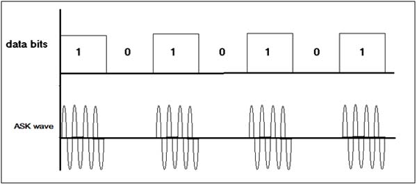
Fig. 1: Image Showing Waveforms for ASK Modulation 

The first Waveform is bit pattern – data bits. 2nd Waveform shows ASK Modulation – for data bit 1 carrier signal (with frequency Fc) present but for data bit 0 there is no carrier signal. Usually carrier frequencies are higher than (100s of KHz) data rate. So in Single bit period several cycles of carrier are transmitted. 

Here given Circuit demonstrates how ASK Modulated wave can be generated. The Circuit is build using IC555. The bit stream can be given as input, and as an output IC555 generates ASK Wave. In this experiment instead of bit-stream, Square pulses are applied as input that can represent Logic High and Logic Low as bit 1 and bit 0. To generate Square pulses one more IC555 is used.

Circuit Description

There are two sections in the circuit

1.      ASK Modulator

2.      1 KHz Pulse Generator

Please refer Circuit Diagram Tab  

Pulse Generator

IC555 is connected in Astable mode. It will generate continuous pulses at 1 KHz frequency. The frequency is determined by RC components R4, R5 and C3 as

F = 1.44 / (R4 + 2×R5) × C3

This 1 KHz pulse output is connected to reset pin (4) input of 2nd IC555 that works as ASK Modulator.

ASK Modulator

As shown in figure IC 555 is configured as Astable Multi vibrator. When its reset pin is high it generates continuous Square pulses with frequency

F = 1.44 / (R1 +2×R2) × C1

And when its reset pin is low its output is also low. The values of R1, R2 and C1 are selected as to get desire carrier frequency. The carrier frequency is selected as 100 KHz. Let us see how values of R1, R2 and C1 are calculated.

Circuit Designing

Assume C1 = 1 nF = 1 × 10⁻⁹ F

Substituting this value in to above equation

F = 1.44 / (R1 + 2×R2) × 10-9

Because desired frequency is 100 KHz

100 × 103 = 1.44 / (R1 + 2×R2) × 10-9

R1 + 2×R2 = 1.44 /( 105 × 10-9)

R1 + 2×R2 = 14400

Now to get around 50% duty cycle R2 > R1, so let us take R1 = 3.3 K.

So

                                                            2×R2 = 14400-3300 = 11100

So                                                        R2 = 5550 = 5.5 K

The nearest practical value can be 5.6 K.

Thus finally R1 = 3.3 K, R2 = 5.6 K and C1 = 1 nF. Instead of selecting fixed value of R1, a Potentiometer is used to tune the frequency and get exact value of 100 KHz.

Similarly we can determine values of R3, R4 and C3 to generate 1 KHz frequency. To find out these values start with assuming C1 = 0.1 µF. So from equation

 F = 1.44 / (R4 + 2×R5) × C3

1000 = 1.44 / (R4 + 2×R5) × 10-7

(R4 + 2×R5) = 1.44 /( 103 × 10-7)

(R4 + 2×R5) = 14400

Again we can select same R4 and R5 values as 3.3 K and 5.6 K respectively. And to get exact 1 KHz frequency we can use Potentiometer instead of fix value resistor for R4.

Circuit Setup

The Circuit can be built on Bread Board or on general purpose PCB.

·         On Bread Board, place all the components and make necessary connections as shown in Circuit Diagram

·         On general purpose PCB, mount and solder all the components and connect components as per Circuit Diagram

Next, apply 5 V to the Circuit through power supply and connect output of Pulse Generator and ASK Modulator to both the channels of DSO (or CRO) using CRO probes.

                                                                               Image of Circuit Setup 

ASK Modulator using IC 555: Circuit Setup

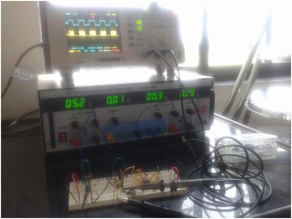
Fig. 2: Image Of Circuit Setup for ASK Modulation 

Circuit Operation

1 KHz pulse input is given to reset pin 4 of IC555. When reset pin is given low logic the internal flip flop resets and IC555 gives low output. When reset pin is high IC555 works normal and generates Square Wave of Frequency determined by RC components in the output. So when bit 1 or logic high is given as input to reset pin a 100 KHz carrier is generated in the output and when bit 0 or logic low is given IC555 gives low output as requirement of ASK Modulated output. 

Here is the Output Image of given Circuit

ASK Modulator using IC 555: Circuit Output

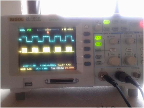
Fig. 3: Image showing Output Result of ASK Modulation

Circuit Diagrams

Circuit-Diagram

Project Components

  • 555 Timer IC
  • Capacitor
  • Potentiometer
  • Resistor


Filed Under: 555 Timers, Electronic Projects
Tagged With: 555 timer circuit, ASK Modulator, IC 555
 

Next Article

← Previous Article
Next Article →

Questions related to this article?
👉Ask and discuss on EDAboard.com and Electro-Tech-Online.com forums.


Tell Us What You Think!! Cancel reply

You must be logged in to post a comment.

EE TECH TOOLBOX

“ee
Tech Toolbox: Internet of Things
Explore practical strategies for minimizing attack surfaces, managing memory efficiently, and securing firmware. Download now to ensure your IoT implementations remain secure, efficient, and future-ready.

EE Learning Center

EE Learning Center
“engineers
EXPAND YOUR KNOWLEDGE AND STAY CONNECTED
Get the latest info on technologies, tools and strategies for EE professionals.

HAVE A QUESTION?

Have a technical question about an article or other engineering questions? Check out our engineering forums EDABoard.com and Electro-Tech-Online.com where you can get those questions asked and answered by your peers!


RSS EDABOARD.com Discussions

  • Switching Frequency For Transformer Design in QR Flyback converter?
  • 12VAC to 12VDC 5A on 250ft 12AWG
  • Estimating Power Budget with Limited Datasheet Information
  • RFsoc4x2 fpga diagram request
  • GanFet power switch starts burning after 20 sec

RSS Electro-Tech-Online.com Discussions

  • An Update On Tarrifs
  • Trying to use a L9110s motor driver chip
  • I want to make a CRT with some modifications But i have no Idea where to start
  • Funny Images Thread!
  • Need Help Figuring Out the Schematics Of Circuit Board

Featured – Designing of Audio Amplifiers part 9 series

  • Basics of Audio Amplifier – 1/9
  • Designing 250 Milli Watt Audio Power Amplifier – 2/9
  • Designing 1 Watt Audio Power Amplifier – 3/9
  • Designing a Bass Boost Amplifier – 4/9
  • Designing a 6 Watt Car Audio Amplifier – 5/9
  • Design a low power amplifier for headphones- 6/9

Recent Articles

  • Fischer connector system adds ratchet locking system designed for 300g shock resistance
  • Littelfuse introduces tactile switch with enhanced bracket peg design for mounting strength
  • Infineon releases GaN switch with monolithic bidirectional design
  • Sienna Semiconductor data converters feature sample rates from 20 to 250 Msps
  • Delta’s 5,500 W power supplies achieve 97.5% energy efficiency for AI servers

EE ENGINEERING TRAINING DAYS

engineering

Submit a Guest Post

submit a guest post
Engineers Garage
  • Analog IC TIps
  • Connector Tips
  • Battery Power Tips
  • DesignFast
  • EDABoard Forums
  • EE World Online
  • Electro-Tech-Online Forums
  • EV Engineering
  • Microcontroller Tips
  • Power Electronic Tips
  • Sensor Tips
  • Test and Measurement Tips
  • 5G Technology World
  • Subscribe to our newsletter
  • About Us
  • Contact Us
  • Advertise

Copyright © 2025 WTWH Media LLC. All Rights Reserved. The material on this site may not be reproduced, distributed, transmitted, cached or otherwise used, except with the prior written permission of WTWH Media
Privacy Policy

Search Engineers Garage

  • Electronics Projects and Tutorials
    • Electronic Projects
      • Arduino Projects
      • AVR
      • Raspberry pi
      • ESP8266
      • BeagleBone
      • 8051 Microcontroller
      • ARM
      • PIC Microcontroller
      • STM32
    • Tutorials
      • Audio Electronics
      • Battery Management
      • Brainwave
      • Electric Vehicles
      • EMI/EMC/RFI
      • Hardware Filters
      • IoT tutorials
      • Power Tutorials
      • Python
      • Sensors
      • USB
      • VHDL
    • Circuit Design
    • Project Videos
    • Components
  • Articles
    • Tech Articles
    • Insight
    • Invention Stories
    • How to
    • What Is
  • News
    • Electronic Product News
    • Business News
    • Company/Start-up News
    • DIY Reviews
    • Guest Post
  • Forums
    • EDABoard.com
    • Electro-Tech-Online
    • EG Forum Archive
  • DigiKey Store
    • Cables, Wires
    • Connectors, Interconnect
    • Discrete
    • Electromechanical
    • Embedded Computers
    • Enclosures, Hardware, Office
    • Integrated Circuits (ICs)
    • Isolators
    • LED/Optoelectronics
    • Passive
    • Power, Circuit Protection
    • Programmers
    • RF, Wireless
    • Semiconductors
    • Sensors, Transducers
    • Test Products
    • Tools
  • Learn
    • eBooks/Tech Tips
    • Design Guides
    • Learning Center
    • Tech Toolboxes
    • Webinars & Digital Events
  • Resources
    • Digital Issues
    • EE Training Days
    • LEAP Awards
    • Podcasts
    • Webinars / Digital Events
    • White Papers
    • Engineering Diversity & Inclusion
    • DesignFast
  • Guest Post Guidelines
  • Advertise
  • Subscribe