Lock bits are set of bits to enable or disable some special security features of a microcontroller. For example, in some cases you might want to disable the memory read functionality of the microcontroller, so that the code you have written cannot be stolen by others. The number of lock bits and their functionality is always given in the datasheet. The controller used here has three lock bits which can be set or reset depending on the feature.
The reader should know the basics of sending and receiving the single byte in programming mode. Refer to 8051 Programmer basics before reading this tutorial.
There are 3 lock bits in the controller 89S51 named as LB1, LB2 and LB3 respectively. The values of each of the lock bit can be either 0 or 1. If it is 0, it is said to be unprogrammed (U) and if it is 1, it is said to be programmed (P). The following table shows the results of programming and unprogramming the different lock bits.
|
ProgramLock Bits
|
Protection Type
|
|||
|
|
LB1
|
LB2
|
LB3
|
|
|
1
|
U
|
U
|
U
|
No program lock features
|
|
2
|
P
|
U
|
U
|
MOVC instructions executed from external program memory are disabled from fetching code bytes from internal memory, EA is sampled and latched on reset, and further programming of the Flash memory is disabled
|
|
3
|
P
|
P
|
U
|
Same asmode 2, but verify is also disabled
|
|
4
|
P
|
P
|
P
|
Same asmode 3, but external execution isalso disabled
|
When the lock bit 1 is programmed the memory reading feature of the controller is disabled, i.e., the memory cannot be read. In case an attempt is made to read the memory after setting the lock bit 1, the buffer will always show the value FF in every memory location. However the microcontroller will carry out its normal operations.
Instructions to set lock bits

Fig. 1: Table listing instructions to set lock bits for 8051 Programmer
The table above shows the instruction corresponding to setting the lock bits. We can either write the lock bits or read the status of lock bits. Reading lock bits is quite simple you have to send the instruction corresponding to the reading lock bit and the fourth byte gives the status of lock bits.
Setting the lock bit is bit tricky. The two bits B1 and B2 in the second byte of the instruction corresponding to write lock bit are used to program or unprogram the lock bits B1 B2 B3.

Fig. 2: Image showing modes of locking bit for 8051 Programmer
The above block shows the bit pattern to program or unprogram the lock bits. The important thing to note here is that at one point of time only one lock bit can be programmed. Also the programming needs to be done sequentially i.e., in order to program the lock bit 3, the lock bit 1 and 2 must be programmed first and hence instruction corresponding to mode1, mode 2 and mode 3 needs to be sent before mode 4.
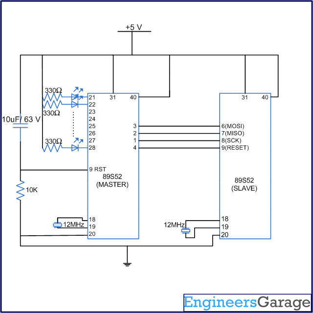
Circuit and Algorithm
Circuit Diagram

Fig. 3: Circuit Diagram of 8051 Programmer
Algorithm
Algorithm to write lock bits:
1. Power on the circuit.
2. Send the instruction for programming enable.
3. Check the 4th byte on MISO pin. If we receive 0x69 this means serial programming mode is enabled.
4. If the serial programming is enabled then send the instruction for setting lock bits to mode1.
5. Send instruction for setting lock bits to mode2.
6. Send instruction for setting lock bits to mode3.
7. Send instruction for setting lock bits to mode4.
Lock bit read Algorithm
1. Power on the circuit.
2. Send the instruction for programming enable.
3. Check the 4th byte on MISO pin. If we receive 0x69 this means serial programming mode is enabled.
4. If the serial programming is enabled then send the instruction for reading the status of lock bits.
Code
Code
The following program is used to set the lock bits of microcontroller.
#include <REG51.h>
#include<intrins.h>
#define port P1

sbit sck=port^0;
sbit res=port^3;
sbit miso=port^1;
sbit mosi=port^2;

bit bit1;
unsigned int i,bitno=0;
unsigned char a,b,c,d;
void delay(unsigned int msec)   // Function for delay
{
	int i,j;
	for(i=0;i<msec;i++)
		for(j=0;j<1275;j++);
}

void sendbit()
{
	mosi=bit1;
	delay(1);
	_nop_();
	sck=1;
	delay(1);
	_nop_();
	sck=0;
}

void sendbyte(unsigned char m)
{
	for(bitno=0;bitno<8;bitno++)
	{
		bit1=m/128;
		m=m<<1;
		sendbit();
	}
}

void main()
{
	i=0;
	sck=0;
	res=1;
	delay(500);

//=======Program enable===========

	a=0xac;
	b=0x53;
	c=0x00;
	d=0x11;
	sendbyte(a);
	sendbyte(b);
	sendbyte(c);
	sendbyte(d);

//===========Lockbit==============

	sendbyte(0xac);
	sendbyte(0xE0);
	sendbyte(0x00);
	sendbyte(0x00);

	sendbyte(0xac);
	sendbyte(0xE1);
	sendbyte(0x00);
	sendbyte(0x00);

	sendbyte(0xac);
	sendbyte(0xE2);
	sendbyte(0x00);
	sendbyte(0x00);

	sendbyte(0xac);
	sendbyte(0xE3);
	sendbyte(0x00);
	sendbyte(0x00);

	res=1;
	while(1);
}
Filed Under: Tutorials


Questions related to this article?
👉Ask and discuss on EDAboard.com and Electro-Tech-Online.com forums.
Tell Us What You Think!!
You must be logged in to post a comment.