The Signature Byte is a unique sequence of bytes which are used to identify the chip. It is written in the memory of the chip during the manufacturing process and cannot be changed. These memory locations are read only. Every chip manufactured by a company with the same number has the same signature byte. For example all the chips with number AT89S51 will have same signature byte.
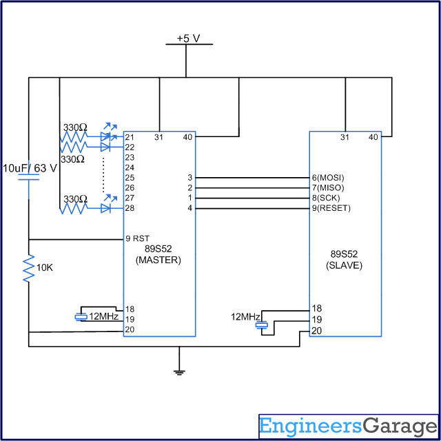
In this project we will generate the pulses from one microcontroller to read the signature byte of the other microcontroller. The output will be displayed on the LEDs and can be verified using the datasheet.
The reader should know the basics of sending and receiving the single byte in programming mode. Refer to 8051 Programmer basics before reading this tutorial.
The location of the memory and the corresponding value where the signature byte is stored is given in the data sheets. By reading the signature byte it is possible to identify the key information about the chip like manufacturer, number etc.
In case of 89S52 the signature byte is of 3 bytes. It is stored in the memory location 0x000, 0x100, 0x200. The values stored at these locations are shown below:
(000H) = 0x1E indicates manufactured by Atmel
(100H) = 52H indicates AT89S52
(200H) = 06H

Fig. 1: Table listing 8051 instructions to read Signature Bytes
The instruction to read Signature Bytes is given in the table above. The first byte in the instruction is fixed. The second and third bytes are used to send the address of the memory location. The value of the signature byte corresponding to the memory location is returned during the transmission of fourth byte. This value is displayed on the LED’s. Please note “x” in the above table mean don’t care condition i.e., either 1 or 0 can be sent. In order to read all the 3 values of signature byte, the same process is repeated three times with different memory locations address.
Circuit and Algorithm
Circuit Diagram

Fig. 2: Circuit Diagram of 8051 Programmer
Algorithm
The algorithm to read the signature byte is:
1. Power on the circuit.
2. Send the instruction for programming enable.
3. Check the 4th byte on MISO pin. If we receive 0x69 this means chip is enabled.
4. If programming mode in enabled then send four bytes instruction corresponding to read first signature byte with address ‘000’.
5. While sending 4th byte, we will receive the value of the 1st signature byte.
6. Repeat the steps 4 and 5 to read the values corresponding to other two memory location of signature byte.
Note: Programming enable instruction is necessary only once. Also in case if the chip is already in the programming enable mode and some other operation like chip erase etc. has been performed, then there is no need to give the programming enable again.
Code
Code
The following code is used to read the signature byte and the output is displayed on LEDs.
#include <REG51.h>
#include<intrins.h>
#define port P1
#define p2 P2

sbit sck=port^0;
sbit res=port^3;
sbit miso=port^1;
sbit mosi=port^2;

bit bit1;
unsigned int i,bitno=0;
unsigned char a,b,c,d,output[13],count;
void delay(unsigned int msec)   // Function for delay
{
	int i,j;
	for(i=0;i<msec;i++)
		for(j=0;j<1275;j++);
}

void read()
{
	bit1=miso;
	output[count]=output[count]<<1;
	if(bit1==1)
		output[count]++;
}

void sread()
{
	count++;
	output[count]=0x00;
	for(bitno=0;bitno<8;bitno++)
	{
		_nop_();
		delay(1);
		_nop_();
		sck=1;
		delay(1);
		_nop_();
		read();
		sck=0;
	}
}

void sendbit()
{
	mosi=bit1;
	delay(1);
	_nop_();
	sck=1;
	delay(1);
	_nop_();
	sck=0;
}

void sendbyte(unsigned char m)
{
	for(bitno=0;bitno<8;bitno++)
	{
		bit1=m/128;
		m=m<<1;
		sendbit();
	}
}

void main()
{
	i=0;
	sck=0;
	res=1;
	p2=0;
	count=-1;
	delay(50);

//=======Program enable===========

	a=0xac;
	b=0x53;
	c=0x00;
	d=0x11;
	sendbyte(a);
	sendbyte(b);
	sendbyte(c);
	sendbyte(d);

//==========Read===================

	sendbyte(0x28);
	sendbyte(0x00);
	sendbyte(0x00);
	sread();

	sendbyte(0x28);
	sendbyte(0x01);
	sendbyte(0x00);
	sread();

	sendbyte(0x28);
	sendbyte(0x02);
	sendbyte(0x00);
	sread();

//========Display=================
	for(i=0;i<3;i++);
	p2=output[i];
	p2=0xff;
	res=1;
	while(1);
}
Filed Under: Tutorials


Questions related to this article?
👉Ask and discuss on Electro-Tech-Online.com and EDAboard.com forums.
Tell Us What You Think!!
You must be logged in to post a comment.