How a multimedia keyboard is made has been already explained in the Atmega 32u4 Based Multimedia Keypad Project. In that project a keypad was designed to control media functions of the window media player on windows OS. A set of tactile switches was used to receive the user inputs in that project. This project – Multimedia Volume Control will control main volume of the windows operating system. Also, in the project, instead of using tactile switches, LDR sensors are used for user inputs to demonstrate a gesture recognition application. Like in the multimedia keypad project, in this project as well, the device will be configured to a consumer device instead on generic desktop control device. In the USB protocol, when the usage page report item of the usage page of an HID device is configured to consumer type, the device gets configured for application specific controls.
The 8-bit USB AVR – Atmega 32u4 is used as the device controller chip in the project. The project uses AVR based Lightweight USB Framework (LUFA) as the firmware which is modified to work like a gesture controlled volume controller.

Fig. 1: Prototype of Arduino Based USB PC Volume Controller
The LUFA firmware is used to implement the USB protocol and its HID device driver class for Consumer controls is modified to program the project. With the use of LUFA firmware, the device driver code to implement USB protocol is not needed to be written explicitly. Modifying the firmware code to implement multimedia functioning respective to the operating system is only challenge in the project. The Volume controller will have four LDR sensors connected to the Arduino board in a vertical fashion. When finger will be swiped from bottom to top, the main (master) volume of the operating system (windows) will increase while when finger will be swiped from top to bottom, the main (master) volume of the operating system (windows) will decrease.
The project uses LDR sensors with transistor circuits for user inputs, Atmega 32u4 as the USB controller chip (on board Arduino Pro Micro) and USB cable to connect with the personal computer.
PREREQUISITES
This project is based on Arduino Pro Micro which has the USB AVR – Atmega 32u4 as the sitting MCU. In order to understand this project, one must have basic knowledge of the AVR microcontrollers and the embedded C programming for AVRs. WinAVR Studio is used to write, edit and compile the project code, so closely following the project shall require familiarizing with the above stated IDE as well. Though LUFA framework takes care of implementing the USB protocol and has APIs to abstract the lower level codes, understanding USB protocol is recommended to understand how actually the project is working. In fact, if anyone has already worked on some other microcontroller, it will not be much pain to understand and follow this project as the project code is more or less about getting input from the GPIO pins of AVR MCU and modifying the LUFA device driver to work as volume controller accordingly.

Fig. 2: Image showing volume control of PC by Arduino based USB device
COMPONENTS REQUIRED
1. Arduino Pro Micro
2. Breadboard
3. Connecting wires
4. LDR
5. BC547 Transistors
6. Micro USB cable
7. 10K resistors
SOFTWARE TOOLS REQUIRED
1. WinAVR Studio
2. AVR Dude

Fig. 3: Block Diagram of Arduino Based USB PC Volume Controller
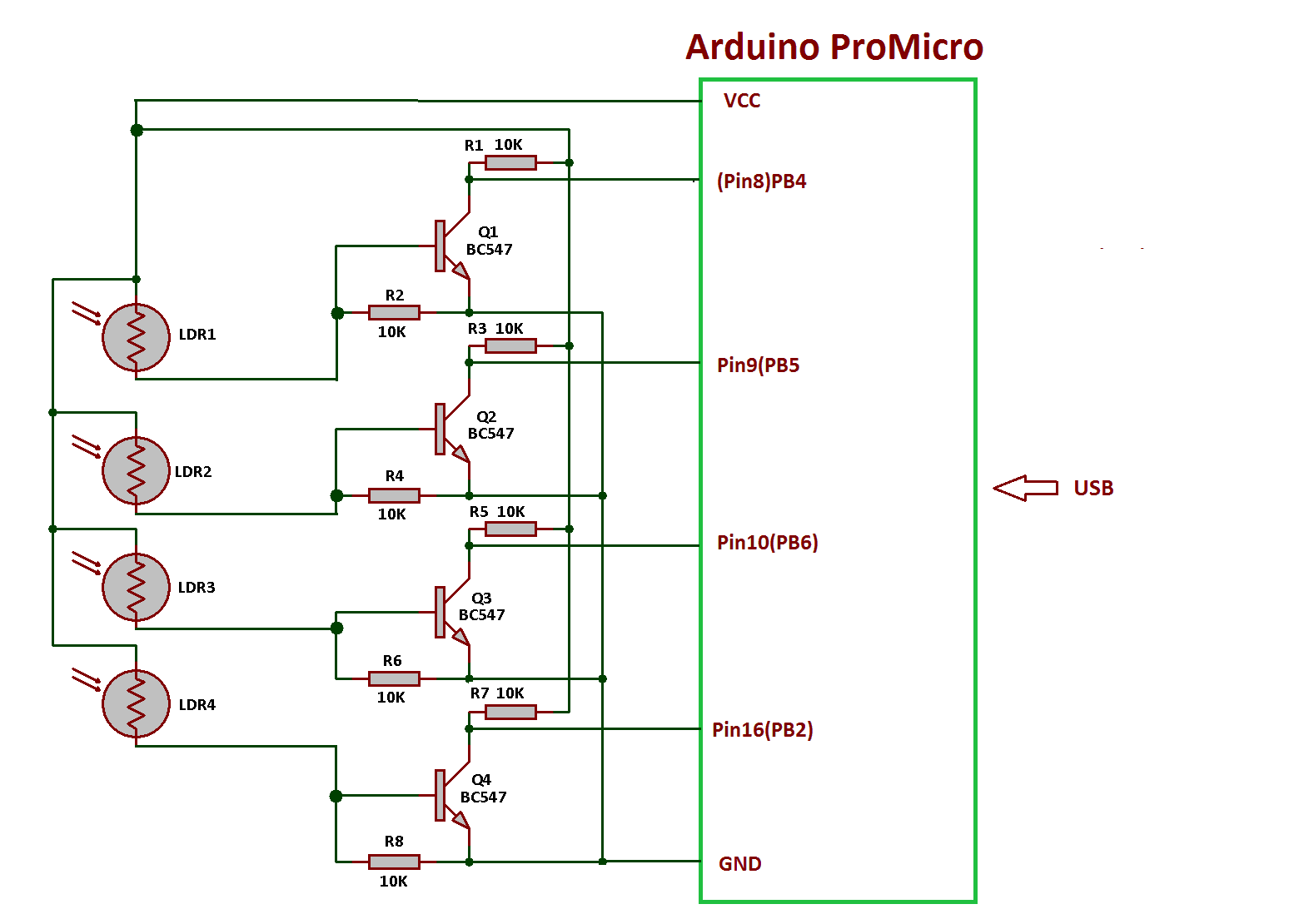
CIRCUIT CONNECTIONS
The project uses Arduino Pro Micro as the USB controller chip. A set of LDR Sensors are connected at the port B of the Arduino. The sensors are connected at pins 2, 4, 5 and 6 of the port B. The LDR sensors have analog output which is converted to digital output by the transistor circuit. The BC547 switching transistors are used for conversion from analog to digital signal. The transistors are connected in the circuit in common base configuration with emitter terminal connected to ground and collector connected to VCC. The output is taken from the collector of the transistors and passed to the pins of port B. The LDR sensors are connected between VCC and the base of transistor.
When LDR sensor will be receiving light in case finger is not obstructing light to it, its resistance remains low and high signal is received at the base of the transistor. So the transistor is biased to remain completely ON and the HIGH signal is bypassed through the emitter and a LOW logic is received at the respective pin of the port B. When LDR sensor will not be receiving light in case finger is obstructing light to it, its resistance remains high and low signal is received at the base of the transistor. So the transistor is biased to remain completely OFF and the HIGH signal is not bypassed through the emitter and a HIGH logic is received at the respective pin of the port B.
The movement of finger is detected from top to down or bottom to up by checking sequence of HIGH logic at the pins of Port B and accordingly volume is controlled.
The Program code for the project is burnt to the Arduino Pro Micro using AVR Dude. The Arduino board is connected to the USB port of a PC by an USB cable.
HOW THE PROJECT WORKS
In this project the USB protocol is implemented by the LUFA framework. For configuring the controller chip to work as Multimedia controller, the HID Class Driver of the LUFA framework is used. The Human Interface Device (HID) class takes care of the transfers between the host device and the human controlled USB peripherals. Any device using HID class sends two reports – usage report and data report to the host device. The reports are a medium at application layer as per the USB protocol to facilitate enumeration and communication between the host and the peripheral device.
In USB protocol the device types are referred by configuring the device to specific controls. The type of controls is set by the usage page report item of the usage report. For configuring to a specific control type, predefined byte(s) code needs to be passed to the usage page report item of the usage page. The different types of controls/device types and the respective byte(s) code that needs to be passed in the usage page report item of the usage page for its configuration are already described in a table in Atmega 32u4 Based Multimedia Keypad Project. Once the usage page report item is defined in the usage report, predefined usage report items are defined in the usage report to configure the device for specific controls corresponding to that usage page or control type.

Fig. 4: Image showing Volume Down function from Arduino Based USB PC Volume Controller
In the LUFA framework, the usage page report item is set by the HID_RI_USAGE_PAGE() macro and usage report items have been set by the HID_RI_USAGE() macros.
For this project the device is configured to be a consumer device by passing 0x0C in the HID_RI_USAGE_PAGE. By configuring to the consumer usage page type, the device is configured to application specific communication on USB. The volume up and down controls used in the project are configured by HID_RI_USAGE() macros in the usage report of LUFA framework where following USB protocol defined codes are passed in the macros -:

Fig. 5: Table listing controls of USB PC Volume Controller and respective Usage Codes
Check out the HID Usage Table provided by the USB Implementers Forum to verify the correction of the codes mentioned here. Check the usage page code for consumer usage page, it is 0x0C and cross check the usage codes in the section for consumer usage page.
In the LUFA framework the HID class related modules are in the LUFA-Source-Folder/LUFA/Drivers/USB/Class/Device folder. These are the device class related modules. The application specific device drivers are in the LUFA-Source-FolderProjects folders. For implementing this project, media controller project in the LUFA projects folder will be modified and complied. The folder contains MediaController.c file which will be modified to implement the project.
How MediaController.c identifies HID device being Consumer Device
The MediaController.c uses MediaControl_HID_Interface interface in HID_Device_USBTask() function which is being imported from the HIDDeviceClass.c (from LUFA-Source-Folder LUFADriversUSBClassDevice) to configure the device as media controller. The interface abstracts the low-level descriptor codes and identifies the device as media control application by an InterfaceNumber variable.
Multimedia Specific Report Descriptors
Any HID device has to exchange data with the host which should be structured in the form of reports. The report descriptor defines the report structure. A report descriptor contains the information needed by host to determine the data format and how the data should be processed by the host. Therefore, a report descriptor basically structure the data that needs to be exchanged with the host according to the USB protocol.
As mentioned before any HID device needs to send usage report and data report descriptors specific to the device type to the host for USB communication. The Usage Report informs the Host about the features or functionality of the USB device whereas the Data (Input) Report is used to transmit the data to the Host.
From Where MediaController.C gets the USAGE and Data Reports Descriptors
In the LUFA framework, the application specific drivers are given the Projects folder. The Multimedia Controller Project is in the LUFA-Source-Folder/Projects/MediaController folder. The MediaController.c imports MediaController.h file in which the data report for media control application is defined in the form of an structure in the following manner -:

Fig. 6: Screenshot of structure defined in MediaController.h
In MediaController.c, a MediaReport[] structure is used in the CALLBACK_HID_Device_CreateHIDReport() function to generate media control specific usage and data reports descriptors. The project imports descriptor.c file also which is given in the same folder. Inside descriptor.c the MediaReport[] structure is assigned the macros used to defined the Usage report items. Therefore the usage report for media control application is defined in the descriptor.c in the following manner -:

Fig. 7: Screenshot of CALLBACK_HID_Device_CreateHIDReport Function from LUFA library
Check that the HID_RI_USAGE_PAGE and HID_RI_USAGE macros have been passed the codes as mentioned in the HID Usage Table.
For the implementation of this project, only Volume Up and Volume Down functions are used.
USAGE REPORT
The Usage report used in the project has the following report items – :
• USAGE_PAGE (CONSUMER) – the consumer control features
• USAGE (VOLUME_UP) – the feature for Volume Up
• USAGE (VOLUME_DOWN) – the feature for Volume Down
• USAGE (PLAY) – play feature
• USAGE (PAUSE) – pause feature
• USAGE (STOP) – stop feature
• USAGE (MUTE) – mute feature
• USAGE (NEXT_TRACK) – next track feature
• USAGE (PREVIOUS_TRACK) – previous track feature
• LOGICAL_MINIMUM (0) – logical zero will mean no key press
• LOGICAL_MAXIMUM (1) – logical one will mean key pressed
These report items are set to following values in descriptor.c file as mentioned before.

Fig. 8: Screenshot of values of report items defined in descriptor.c
The Usage or Feature report contains information about the features of the device. In other words, this report informs Host about the features needed in the device. The Host can access this report by requesting the device using GET_REPORT request. This report is transmitted using Control Transfer Type of the USB protocol.
DATA (INPUT) REPORT
The Data (Input) Report contains the data that needs to be transmitted to the Host. It contains data related to the features selected via the Usage Report. In MediaController.h a structure for data report of the media control application is defined in the following manner as mentioned before.
Fig. 9: Screenshot of structure defined in MediaController.h
The data report sends 11 bytes where each byte goes for setting logical maximum or logical minimum for Play, Pause, Fast Forward, Rewind, Next Track, Previous Track, Stop, Play or Pause, Mute, Volume Up and Volume Down functions. It can be seen from the Usage report also that Report Count item is set to 0x0B (decimal 11) by the HID_RI_REPORT_COUNT macro.
HOW THE DEVICE WORKS
The AVR microcontroller is programmed to detect HIGH logic in specific sequences (Bottom to Up or Top to Down) according to the circuit connections of the LDR sensors. The main() function and the CALLBACK_HID_Device_CreateHIDReport() function of the MediaController.c are modified to detect sequence of HIGH logic across the pins of Port B and alter volume Up or Volume Down report item in the past data report to the host on USB. Check out the program code to see the modifications done to the MediaController.c file for implementing the project.
PROGRAMMING GUIDE
For building the project download the LUFA framework from the github.com. The application project provided with the LUFA framework is modified to make this project. In the extracted LUFA zip file, open LUFA-Source-Folder/Projects/MediaController folder. The folder has the following files and folders.

Fig. 10: Screenshot of LUFA library folder on Windows
Of these, MediaController.h, MediaController.c and Makefile needs to be modified for this project. The modified files (provided at the bottom of the article in zip format) can also be downloaded from the engineersgarage and replaced with the original files. Either open the files in WinAVR Studio or Notepad++ and modify original files or replace files with the already modified one. The modified or replaced MediaController.c needs to be compiled from within the LUFA’s Source folder to get the object code.
Modifying MediaController.h
The MediaController.h library file is imported in the MediaController.c file and includes a set of additional libraries and the definitions for constants and functions for the media control application. These include the additional libraries for the joystick, button and LEDs which should be commented out as the project is not using these HID features. So open MediaController.h and make the following changes – :
• Comment the #include library statements for Joystick.h, LEDS.h, and Buttons.h (These libraries are commented as any joystick, buttons board and LED board is not used in the project)
Save the file with changes.
Modifying MediaController.C file
Again in the MediaController.c, the code sections for Joystick, button board and LEDs need to be commented out. So open MediaController.c and make the following changes -:
• In the main loop, comment the LEDs_SetAllLEDs()
• In SetupHardware() function, comment the Joystick_Init(), LEDs_Init(), Buttons_Init()
• In EVENT_USB_Device_Connect() function, comment the LEDs_SetAllLEDs()
• In EVENT_USB_Device_Disconnect() function, comment LEDs_SetAllLEDs()
• In EVENT_USB_Device_ConfigurationChanged() function, comment the LEDs_SetAllLEDs()
In MediaController.c the main() function executes the functioning of the application. Inside the main function Port B where LDR sensors have been connected needs to be defined as input and all the pins of port B has to be raised to LOW logic by default as the microcontroller will need to detect HIGH logic as user input. So add the following statements in the beginning of main() function – :
Inside the infinite for loop the HID_Device_USBTask() function is called where MediaControl_HID_Interface interface is passed as parameter. The interface identifies the device as Media Control Application and abstracts the low level program code specific to Consumer HID class. The function HID_Device_USBTask() is coming from the HIDClassDevice.c module (located in LUFA/Drivers/USB/Class/Device/HIDClassDevice.c) and is used for general management task for a given HID class interface, required for the correct operation of the interface. It should be called in the main program loop, before the master USB management task USB_USBTask(). The USB_USBTask() is the main USB management task. The USB driver requires this task to be executed continuously when the USB system is active (device attached in host mode, or attached to a host in device mode) in order to manage USB communications. The function USB_USBTask() is defined in USBTask.c (Located in LUFA-Source-FolderLUFADriversUSBCore folder).
For sending the required Data (Input) reports CALLBACK_HID_Device_CreateHIDReport() needs to be modified. The default file has the function body to detect joystick movement as well.

Fig. 11: Screenshot of CALLBACK_HID_Device_CreateHIDReport Function in LUFA Library
This project is sequence of HIGH logic at pins of Port B to decide whether volume has to be increased to decreased. Therefore, HIGH bit at each pin is detected by a sequence and the volume up or volume down report item of the data report is modified accordingly. So replace the body of the function with the following code -:
In the body Boolean variables are declared to detect HIGH or LOW logic at the pins. The _BV() function is used to map the respective bit as a byte with only the respective bit changed in the returned byte.
The HIGH logic is detected in specific sequences on Port B pins and volume up or volume down data report item is modified to execute the increasing or decreasing main volume functions respectively.
Save the file and create Make file for the project.
Modifying Make File
In the MediaController folder there is a make file that needs to be edited. The file can be edited using Notepad++. The following information needs to be edited.
• MCU = atmega32u4
• ARCH = AVR8
• BOARD = LEONARDO
• F_CPU = 16000000
Save the file and exit. Now all the files are edited completely for the volume controller application.
Compiling MediaController.c
For compiling the source code, WinAVR Programmers Notepad or Arduino IDE can be used. Open the modified MediaController.c file and compile the code.
BURNING HEX CODE
The hex file is generated on compiling the MediaController.c file. For burning the object code to microcontroller open the Command Prompt, change the current directory to the directory containing the Hex file. This can be done using command: CD <address of the directory>. Now reset the Arduino and instantly run the command: : : avrdude -v -p atmega32u4 -c avr109 -P COM20 -b 57600 -D -Uflash:w:MediaController.hex:i after replacing the COM Port with the recognized one.
If the uploading process is successful, the Arduino will be shown as HID Consumer Control Device in the Device Manager. There is no need of installing any driver in the computer as Generic HID driver is used for the project implementation.
Connect the device with a windows PC and swipe finger top to down or bottom to up to check whether system volume is decreasing or increasing on the respective actions.
In the next project – Atmega 32u4 based UART to USB converter, learn how to make a UART to USB converter on Arduino Pro Micro.
You may also like:


Project Source Code
###
/* LUFA Library Copyright (C) Dean Camera, 2015. dean [at] fourwalledcubicle [dot] com www.lufa-lib.org */ /* Copyright 2015 Dean Camera (dean [at] fourwalledcubicle [dot] com) Permission to use, copy, modify, distribute, and sell this software and its documentation for any purpose is hereby granted without fee, provided that the above copyright notice appear in all copies and that both that the copyright notice and this permission notice and warranty disclaimer appear in supporting documentation, and that the name of the author not be used in advertising or publicity pertaining to distribution of the software without specific, written prior permission. The author disclaims all warranties with regard to this software, including all implied warranties of merchantability and fitness. In no event shall the author be liable for any special, indirect or consequential damages or any damages whatsoever resulting from loss of use, data or profits, whether in an action of contract, negligence or other tortious action, arising out of or in connection with the use or performance of this software. */ /** file * * Main source file for the MediaControl project. This file contains the main tasks of * the demo and is responsible for the initial application hardware configuration. */ #include "MediaController.h" /** Buffer to hold the previously generated Media Control HID report, for comparison purposes inside the HID class driver. */ static uint8_t PrevMediaControlHIDReportBuffer[sizeof(USB_MediaReport_Data_t)]; /** LUFA HID Class driver interface configuration and state information. This structure is * passed to all HID Class driver functions, so that multiple instances of the same class * within a device can be differentiated from one another. */ USB_ClassInfo_HID_Device_t MediaControl_HID_Interface = { .Config = { .InterfaceNumber = INTERFACE_ID_HID, .ReportINEndpoint = { .Address = MEDIACONTROL_HID_EPADDR, .Size = MEDIACONTROL_HID_EPSIZE, .Banks = 1, }, .PrevReportINBuffer = PrevMediaControlHIDReportBuffer, .PrevReportINBufferSize = sizeof(PrevMediaControlHIDReportBuffer), }, }; /** Main program entry point. This routine contains the overall program flow, including initial * setup of all components and the main program loop. */ int main(void) { SetupHardware(); DDRB = 0x00; DDRF = 0x00; //LEDs_SetAllLEDs(LEDMASK_USB_NOTREADY); GlobalInterruptEnable(); for (;;) { HID_Device_USBTask(&MediaControl_HID_Interface); USB_USBTask(); } } /** Configures the board hardware and chip peripherals for the demo's functionality. */ void SetupHardware() { #if (ARCH == ARCH_AVR8) /* Disable watchdog if enabled by bootloader/fuses */ MCUSR &= ~(1 << WDRF); wdt_disable(); /* Disable clock division */ clock_prescale_set(clock_div_1); #endif /* Hardware Initialization */ //Joystick_Init(); //LEDs_Init(); //Buttons_Init(); USB_Init(); } /** Event handler for the library USB Connection event. */ void EVENT_USB_Device_Connect(void) { //LEDs_SetAllLEDs(LEDMASK_USB_ENUMERATING); } /** Event handler for the library USB Disconnection event. */ void EVENT_USB_Device_Disconnect(void) { //LEDs_SetAllLEDs(LEDMASK_USB_NOTREADY); } /** Event handler for the library USB Configuration Changed event. */ void EVENT_USB_Device_ConfigurationChanged(void) { bool ConfigSuccess = true; ConfigSuccess &= HID_Device_ConfigureEndpoints(&MediaControl_HID_Interface); USB_Device_EnableSOFEvents(); //LEDs_SetAllLEDs(ConfigSuccess ? LEDMASK_USB_READY : LEDMASK_USB_ERROR); } /** Event handler for the library USB Control Request reception event. */ void EVENT_USB_Device_ControlRequest(void) { HID_Device_ProcessControlRequest(&MediaControl_HID_Interface); } /** Event handler for the USB device Start Of Frame event. */ void EVENT_USB_Device_StartOfFrame(void) { HID_Device_MillisecondElapsed(&MediaControl_HID_Interface); } /** HID class driver callback function for the creation of HID reports to the host. * * param[in] HIDInterfaceInfo Pointer to the HID class interface configuration structure being referenced * param[in,out] ReportID Report ID requested by the host if non-zero, otherwise callback should set to the generated report ID * param[in] ReportType Type of the report to create, either HID_REPORT_ITEM_In or HID_REPORT_ITEM_Feature * param[out] ReportData Pointer to a buffer where the created report should be stored * param[out] ReportSize Number of bytes written in the report (or zero if no report is to be sent) * * return Boolean c true to force the sending of the report, c false to let the library determine if it needs to be sent */ bool CALLBACK_HID_Device_CreateHIDReport(USB_ClassInfo_HID_Device_t* const HIDInterfaceInfo, uint8_t* const ReportID, const uint8_t ReportType, void* ReportData, uint16_t* const ReportSize) { USB_MediaReport_Data_t* MediaReport = (USB_MediaReport_Data_t*)ReportData; /* Flags to indicate LDR has been obstructed * or finger has been placed over it */ static bool LDR1_obstruct_flag; static bool LDR2_obstruct_flag; static bool LDR3_obstruct_flag; static bool LDR4_obstruct_flag; /* check if LDR 1 is obstructed * if obstructed, check for other LDR flags * if other flags are set, then it is the case of up motion * modify the data report for volume up command * else set the LDR1 flag, it may be the starting of down motion */ if(PINB & _BV(PB4)) { if(LDR4_obstruct_flag && LDR3_obstruct_flag && LDR2_obstruct_flag) { MediaReport->VolumeUp = 1; // update report with VolumeUp // reset all flags LDR1_obstruct_flag = 0; LDR2_obstruct_flag = 0; LDR3_obstruct_flag = 0; LDR4_obstruct_flag = 0; } else { LDR1_obstruct_flag = 1; // set the flag // reset all other flags LDR2_obstruct_flag = 0; LDR3_obstruct_flag = 0; LDR4_obstruct_flag = 0; } } /* check if LDR 2 is obstructed * if obstructed, set the flag */ if(PINB & _BV(PB5)) { LDR2_obstruct_flag = 1; // set the flag } /* check if LDR 3 is obstructed * if obstructed, set the flag */ if(PINB & _BV(PB6)) { LDR3_obstruct_flag = 1; // set the flag } /* check if LDR 3 is obstructed * if obstructed, check for other LDR flags * if other flags are set, then it is the case of down motion * modify the data report for volume down command * else set the LDR4 flag, it may be the starting of up motion */ if(PINB & _BV(PB2)) { if(LDR3_obstruct_flag && LDR2_obstruct_flag && LDR1_obstruct_flag) { MediaReport->VolumeDown = 1; // update report with VolumeDown // reset all flags LDR1_obstruct_flag = 0; LDR2_obstruct_flag = 0; LDR3_obstruct_flag = 0; LDR4_obstruct_flag = 0; } else { LDR4_obstruct_flag = 1; // set the flag // reset all other flags LDR1_obstruct_flag = 0; LDR2_obstruct_flag = 0; LDR3_obstruct_flag = 0; } } *ReportSize = sizeof(USB_MediaReport_Data_t); return false; } /** HID class driver callback function for the processing of HID reports from the host. * * param[in] HIDInterfaceInfo Pointer to the HID class interface configuration structure being referenced * param[in] ReportID Report ID of the received report from the host * param[in] ReportType The type of report that the host has sent, either HID_REPORT_ITEM_Out or HID_REPORT_ITEM_Feature * param[in] ReportData Pointer to a buffer where the received report has been stored * param[in] ReportSize Size in bytes of the received HID report */ void CALLBACK_HID_Device_ProcessHIDReport(USB_ClassInfo_HID_Device_t* const HIDInterfaceInfo, const uint8_t ReportID, const uint8_t ReportType, const void* ReportData, const uint16_t ReportSize) { // Unused (but mandatory for the HID class driver) in this demo, since there are no Host->Device reports }###
Circuit Diagrams
Project Datasheet
Filed Under: Electronic Projects, Tutorials

Questions related to this article?
👉Ask and discuss on EDAboard.com and Electro-Tech-Online.com forums.
Tell Us What You Think!!
You must be logged in to post a comment.