In one of the previous projects – Atmega 32u4 Based Composite Keyboard Mouse Project, a composite device was made. A composite device is a device that has functions of two devices on the same hardware like the composite keyboard mouse was able to operate as generic keyboard as well as generic mouse. In this project, again a composite device – Virtual Serial Mouse is designed. The device works like a mouse as well as an UART to USB converter. The making of a mouse has been already explained in the Atmega 32u4 Based USB Mouse Project. Similarly, making of an UART to USB converter has been explained in Atmega 32u4 Based UART to USB Converter Project. The 8-bit USB AVR – Atmega 32u4 is used as the controller chip in this project. The AVR based Lightweight USB Framework (LUFA) is used as the firmware which is modified and loaded to the Arduino board for making the project.
The device uses both the Communication Device Class (CDC) and Human Interface Device (HID) type interfaces of the USB protocol. The drivers for both the interfaces are taken from the LUFA framework. By using the LUFA firmware, the device driver code to implement USB protocol for CDC and HID class as well as the UART protocol is not needed to be written explicitly. By using APIs provided in the open source framework, the CDC and HID class protocols are implemented.

Fig. 1: Prototype of Arduino based Composite USB Serial Mouse
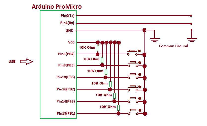
For operating as Serial device the project device receives the USB data from the USB port of the Arduino Pro Micro. For connecting to UART interface, Tx and Rx pins of the Arduino Pro Micro are connected with the UART interface of any other embedded device. For working as mouse the device is provided with buttons. The tactile switches are used as buttons which are interfaced to Port B of the Arduino Board. As a mouse, the device has buttons for the following functions – :
• Move Pointer Left
• Move Pointer Right
• Move Pointer Upwards
• Move Pointer Down
• Right Click
• Left Click
PREREQUISITES
This project is based on Arduino Pro Micro which has the USB AVR – Atmega 32u4 as the sitting MCU. In order to understand this project, one must have basic knowledge of the AVR microcontrollers and the embedded C programming for AVRs. WinAVR Studio is used to write, edit and compile the project code, so closely following the project shall require familiarizing with the above stated IDE as well. Though LUFA framework takes care of implementing the USB protocol for CDC as well as HID Class and the UART protocol. Though the framework has APIs to abstract the lower level codes, understanding USB protocol is recommended to understand how actually the project is working. In fact, if anyone has already worked on some other microcontroller, it will not be much pain to understand and follow the project. The project is based on using APIs of the LUFA framework and modifying the demo files that comes with the framework itself.

Fig. 2: Screenshot of Virtual Serial Function
COMPONENTS REQUIRED
1. Arduino Pro Micro
2. Breadboard
3. Connecting wires
4. Push buttons
5. Micro USB cable
6. 10K resistors
SOFTWARE TOOLS REQUIRED
1. WinAVR Studio
2. AVR Dude
BLOCK DIAGRAM

Fig. 3: Block Diagram of Arduino based Composite USB Serial Mouse
CIRCUIT CONNECTIONS
The project is built on Arduino Pro Micro in which Atmega 32u4 works as the controller chip. The USB to UART and UART to USB protocol conversion is carried out on the Arduino board itself. The Arduino board has in-built USB port to connect with the personal computer and has Tx and Rx pins for serial communication on UART. For working as serial device only the Arduino board is sufficient and connecting wires for connecting with embedded device having UART interface and USB cable for connecting with the PC are required.
For working as mouse, a set of six tactile switches are connected at the port B of the Arduino. The switches are connected at pins 1, 3, 2, 6, 5 and 4 of the port B with functions assigned to them according to the following table – :

Fig. 4: Table listing Arduino pins and respective mouse functions
The Program code for the project is burnt to the Arduino Pro Micro using AVR Dude. The Arduino board is connected to the USB port of a PC by a USB cable and for connecting to UART interface of another embedded device, RS-232 cable is needed.
HOW THE PROJECT WORKS
In this project both USB protocol for CDC as well as HID class and the UART protocol are used and an API of virtual serial mouse from the LUFA framework is used to implement the project. The device is configured to communication device class (CDC) as well as HID class device. For USB to USART and USART to USB conversion, the device is configured to Abstract Control Model Subclass.
The project is USB CDC as well as HID class device. In the LUFA framework CDC class related modules along with HID and other class related modules are in the LUFA-Source-Folder /LUFA/Drivers/USB/Class/Device folder. The LUFA framework has demo projects for different USB device classes in the LUFA-Source-FolderDemosDeviceClassDriver folder. For implementing the project, demo project for virtual serial mouse provided in the LUFA framework will be modified and complied. The demo project for virtual serial mouse is in the LUFA-Source-FolderDemosDeviceClassDriverVirtualSerialMouse folder. The folder contains VirtualSerialMouse.c file which will be modified to implement the project.

Fig. 5: Image showing characters sent from Arduino to PC via Serial Device
How VirtualSerialMouse.c identifies device as a composite CDC and HID Device
The VirtualSerialMouse.c uses two interfaces – VirtualSerial_CDC_Interface interface called in CDC_Device_USBTask () function where the function is imported from the CDCDeviceClass.c (from LUFA-Source-Folder LUFADriversUSBClassDevice) to configure the device as USB CDC device and Mouse_HID_Interface interface called in HID_Device_USBTask() function where the function is imported from the HIDDeviceClass.c (file located in LUFA-Source-Folder LUFADriversUSBClassDevice) to configure the device as mouse. The interfaces abstract the low-level descriptor codes and identifies the device as CDC device or HID device through an InterfaceNumber variable.
USB CDC Specific Descriptors
Any USB device configure and exchange data with the host by sending descriptors in response to requests from the host device. At application layer descriptors are structured in the form of reports. Every report descriptor has a report structure. A report descriptor contains the information needed by host to determine the data format and how the data should be processed by the host. Therefore, a report descriptor basically structure the data that needs to be exchanged with the host according to the USB protocol.
When a USB device is connected to the host computer, the host sends request for configuration in the form of control transfer. This is common for all USB peripherals or devices irrespective of their configuration to any specific USB device class. Any CDC device for configuring with a host has to respond with Class Request, Class Notification and Endpoint Configuration. These information are passed through the Usage report to the host as the Usage Report informs the Host about the features or functionality of the USB device.
Similarly for configuring as mouse, like a mouse, the device will have to send usage report and data report descriptors specific to mouse HID Class to the host. The Usage or Feature report for mouse contains the information related to the HID features of the mouse. For example, a Mouse feature report generally contains information about number of buttons used, number of axis, scroll wheel, size of Data Report, minimum/maximum movement etc. In other words, this report informs the Host about the type of features needed in the device. The Host can access this report by requesting the device using GET_REPORT request. This report is transmitted using Control Transfer Type of the USB protocol.
The usage and data report associated with CDC USB devices are defined in the CDCClassCommon.h file in the LUFA framework. The file is located in the LUFA-Source-Folder/LUFA/Drivers/USB/Class/Common folder. In the usage report, a CDC device has to acknowledge its class, subclass and protocol values. To learn more about the usage report and data report associated with CDC class USB devices and how various descriptors are formatted and sent to the host on request for CDC device, refer to the Atmega 32u4 Based UART to USB Converter Project.
Similarly, to learn about the usage and data report associated with mouse device, refer to Atmega 32u4 Based USB Mouse Project.
From Where VirtualSerialMouse.C gets the USAGE and Data Report Descriptors
In the LUFA framework’s demo project for Virtual Serial, VirtualSerialMouse.c file imports VirtualSerialMouse.h where the descriptors.h is imported. The descriptor.h has the structures defining CDC class related descriptors. The VirtualSerialMouse.c imports VirtualSerialMouse.h which imports usb.h. USB.h imports CDCCLass.h and HIDClass.h. In CDCClass.h is imported CDCClassDevice.h. The CDCClassDevice.h imports CDCClassCommon.h where the CDC device specific descriptor fields have been defined. In HIDClass.h is imported HIDClassDevice.h. The HIDClassDevice.h imports HIDClassCommon.h where the HID device specific descriptor fields for keyboard, mouse and joystick have been defined.
HOW THE DEVICE WORKS
The device needs to be connected between the PC and the embedded system having UART interface. By default the device works as a mouse but when another embedded system is connected through UART, it becomes UART to USB converter. In the project code additional library for UART is imported for UART functionality. The main() function of the VirtualSerialMouse.c is modified to work the device like a protocol changer. In the main function itself, the device is also configured to HID mouse. The CALLBACK_HID_Device_CreateHIDReport() function is modified to make the device work as generic mouse. Check out the program code to see the modifications implemented for building the project.

Fig. 6: Image of Arduino based Composite USB Serial Mouse
PROGRAMMING GUIDE
For building the project download the LUFA framework from the github.com. The demo project provided with the LUFA framework is modified to make the device. In the extracted LUFA zip file, open Demos/Device/ClassDriver/VirtualSerialMouse folder. The folder has the following files and folders.

Fig. 7: Screenshot of LUFA Library Folder on Windows
Of these, VirtualSerialMouse.h, VirtualSerialMouse.c and Makefile needs to be modified for the project.The modified files (provided at the bottom of the article in zip format) can also be downloaded from the engineersgarage and replaced with the original files. Either open the files in WinAVR Studio or Notepad++ and modify original files or replace files with the already modified one. The modified or replaced VirtualSerialMouse.c needs to be compiled from within the LUFA’s Source folder to get the object code.
Modifying VirtualSerialMouse.h
The VirtualSerialMouse.h library file is imported in the VirtualSerialMouse.c file and includes a set of additional libraries and defines the constants and functions for the joystick device. These include the additional libraries for the joystick, button and LEDs which should be commented out as the project is not using these features. So open VirtualSerialMouse.h and make the following changes – :
• Comment the #include library statements for Joystick.h, LEDS.h, and (We are commenting these libraries as we are not using any joystick, buttons board and LED board)
• Comment the #define statements for LEDMASK_USB_NOTREADY, LEDMASK_USB_ENUMERATING, LEDMASK_USB_READY, LEDMASK_USB_ERROR
• Delete the function declaration for CheckJoystickMovement Save the file with changes
Modifying VirtualSerialMouse.C fileAgain in the VirtualSerialMouse.c, the code sections for Joystick, button board and LEDs need to be commented out. So open VirtualSerialMouse.c and make the following changes – :
• In the main loop, comment the LEDs_SetAllLEDs()
• In SetupHardware() function, comment the Joystick_Init(), LEDs_Init()
• In EVENT_USB_Device_Connect() function, comment the LEDs_SetAllLEDs()
• In EVENT_USB_Device_Disconnect() function, comment LEDs_SetAllLEDs()
• In EVENT_USB_Device_ConfigurationChanged() function, comment the LEDs_SetAllLEDs()
• Also delete the CheckJoystickMovement function completely
In VirtualSerialMouse.c the main() function executes the functioning of the protocol convertor device and also configures the device to HID mouse. First uart.h has to be included in the VirtualSerialMouse.c So add the following statements in the beginning of file.
#include “VirtualSerial.h”
The following functions defined in the uart.h will be used in the program code – :

Fig. 8: Table listing functions defined in uart.h
In the main() function, a variable OUT_Data to hold data sent by the host needs to be defined and a character buffer buff[] to hold data from UART has to be defined. The array representing character buffer has to set its last element as NULL character and UART has to be initialized using uart_init() function. A file variable has to be defined to contain data received from the USB port. This has to be used as parameter in CDC_Device_CreateStream() function. The CDC_Device_CreateStream() function is defined in the CDCClassDevice.c file where other CDC Class Device related functions are also defined. The CDCClassDevice.c is located in the LUFA-Source-FolderLUFAUSBClassDevice folder. An infinite for loop is called in which data from USB port is assigned to OUT_Data variable using getc() function and is sent Tx pin of UART using uart_char() function. If any data from embedded device through UART is available, it is read through uart_read() function and is assigned to the buff[]. The data in buff[] is taken into ReportString pointer and sent to the computer using fputs() function.
For configuring to HID mouse, Port B where the tactile switches have been connected needs to be defined as input and all the pins of port B has to be raised to HIGH logic by default as the microcontroller will need to detect LOW logic for input from tactile switches. So replace the original body of the main function from the following code – :
int main(void)
Inside the infinite for loop the CDC_Device_USBTask() function is called where VirtualSerial_CDC_Interface interface is passed as parameter. The interface identifies the device as Virtual Serial device and abstracts the low level program code specific to CDC subclass. The function is coming from the CDCClassDevice.c module (located in LUFA/Drivers/USB/Class/Device/CDCClassDevice.c) and is used for general management task for a given CDC class interface, required for the correct operation of the interface.
Similarly, Inside the infinite for loop the HID_Device_USBTask() function is also called where Mouse_HID_Interface interface is passed as parameter. The interface identifies the device as mouse and abstracts the low level program code specific to mouse HID class. The function is coming from the HIDClassDevice.c module (located in LUFA/Drivers/USB/Class/Device/HIDClassDevice.c) and is used for general management task for a given HID class interface, required for the correct operation of the interface.
Both CDC_Device_USBTask() and HID_Device_USBTask() should be called in the main program loop, before the master USB management task USB_USBTask(). The USB_USBTask() is the main USB management task. The USB driver requires this task to be executed continuously when the USB system is active (device attached in host mode, or attached to a host in device mode) in order to manage USB communications. The function is defined in USBTask.c (Located in LUFA-Source-FolderLUFADriversUSBCore folder).
For creating Mouse Data report CALLBACK_HID_Device_CreateHIDReport() needs to be modified. The default file has the function body to detect joystick movement and click on button board.

Fig. 9: Screenshot of CALLBACK_HID_Device_CreateHIDReport Function in LUFA Library
This mouse project is using tactile switches to feed directional and button inputs. Therefore, LOW bit at each button is detected and the corresponding field value in data report for mouse is changed accordingly. So replace the body of the function with the following code.
bool
In the body _BV() function is used to map the respective bit as a byte with only the respective bit changed in the returned byte.
Save the file and create Make file for the project.
Modifying Make File
In the VirtualSerialMouse folder there is a make file that needs to be edited. The file can be edited using Notepad++. The following information needs to be edited – :
• MCU = atmega32u4
• ARCH = AVR8
• BOARD = LEONARDO
• F_CPU = 16000000
Save the file and exit. Now all the files are edited completely for the composite device.
Compiling VirtualSerialMouse.c
For compiling the source code, WinAVR Programmers Notepad or Arduino IDE can be used. Open the modified VirtualSerialMouse.c file and compile the code.
BURNING HEX CODE
The hex file is generated on compiling the VirtualSerialMouse.c file. For burning the object code to microcontroller open the Command Prompt, change the current directory to the directory containing the Hex file. This can be done using command: CD <address of the directory>. Now reset the Arduino and instantly run the command: : avrdude -v -p atmega32u4 -c avr109 -P COM20 -b 57600 -D -Uflash:w:VirtualSerialMouse.hex:i after replacing the COM Port with the recognized one.
INSTALLING DRIVERS
After successful burning, plug the device. If the device is not properly installed or detected, then device driver needs to be installed at Host end. The VirtualSerialMouse folder contains LUFA VirtualSerialMouse.inf file. Install the device driver with this inf file. The driver can be installed from the Device Manager. After the driver is successfully installed, the device will be shown as LUFA CDC Demo under Ports tab and HID Mouse under Mice tab in the Device Manager.
Testing the device as UART to USB Converter
For UART System (Peripheral) to Host communication testing, any Arduino Board can be used that can transmit characters to the Atmega32u4 via UART. The Tx pin of Arduino and the Rx pin of Atmega32u4 needs to be connected for testing. The Atmega32u4 will transmit these received characters to the Host via USB. Any Serial monitor like RealTerm can be used at Host end to see the incoming data from the Virtual Serial Device.
The following program code can be loaded to any Arduino board for UART to Host test.
void setup() {
For Host to UART System (Peripheral) communication testing, any Arduino Mega2560 board can be used that can receive characters from the Atmega32u4 via UART. The Mega board has three serial ports. The data on Serial port0 can be seen on PC. A program can be build that can receive characters from the ATmega32u4 via UART port1 and will forward these characters to the UART port0. The Rx pin of Arduino and the Tx pin of Atmega32u4 needs to be connected for testing. The Arduino needs to be connected via USB to the PC to see the data at port0. For testing, transmit some characters from the RealTerm Serial monitor connected to Virtual Serial device. If the device is working properly, the received characters can be seen on Arduino Serial monitor connected to Arduino device.
The following program code can be loaded to Arduino Mega2560 for Host to UART test.
void setup() {
Testing the Device as USB Mouse
For testing the device as mouse, when the device is connected to the PC through a USB cable, press buttons to check if device is operating like a mouse or not.
In the next project – Atmega 32u4 Based Wireless Keyboard, a wireless keyboard using AVR controller and LUFA framework will be made.
Project Source Code
###
/* LUFA Library Copyright (C) Dean Camera, 2015. dean [at] fourwalledcubicle [dot] com www.lufa-lib.org */ /* Copyright 2015 Dean Camera (dean [at] fourwalledcubicle [dot] com) Permission to use, copy, modify, distribute, and sell this software and its documentation for any purpose is hereby granted without fee, provided that the above copyright notice appear in all copies and that both that the copyright notice and this permission notice and warranty disclaimer appear in supporting documentation, and that the name of the author not be used in advertising or publicity pertaining to distribution of the software without specific, written prior permission. The author disclaims all warranties with regard to this software, including all implied warranties of merchantability and fitness. In no event shall the author be liable for any special, indirect or consequential damages or any damages whatsoever resulting from loss of use, data or profits, whether in an action of contract, negligence or other tortious action, arising out of or in connection with the use or performance of this software. */ /** file * * Main source file for the VirtualSerialMouse demo. This file contains the main tasks of * the demo and is responsible for the initial application hardware configuration. */ #include "VirtualSerialMouse.h" #include "uart.h" /** LUFA CDC Class driver interface configuration and state information. This structure is * passed to all CDC Class driver functions, so that multiple instances of the same class * within a device can be differentiated from one another. */ USB_ClassInfo_CDC_Device_t VirtualSerial_CDC_Interface = { .Config = { .ControlInterfaceNumber = INTERFACE_ID_CDC_CCI, .DataINEndpoint = { .Address = CDC_TX_EPADDR, .Size = CDC_TXRX_EPSIZE, .Banks = 1, }, .DataOUTEndpoint = { .Address = CDC_RX_EPADDR, .Size = CDC_TXRX_EPSIZE, .Banks = 1, }, .NotificationEndpoint = { .Address = CDC_NOTIFICATION_EPADDR, .Size = CDC_NOTIFICATION_EPSIZE, .Banks = 1, }, }, }; /** Buffer to hold the previously generated Mouse HID report, for comparison purposes inside the HID class driver. */ static uint8_t PrevMouseHIDReportBuffer[sizeof(USB_MouseReport_Data_t)]; /** LUFA HID Class driver interface configuration and state information. This structure is * passed to all HID Class driver functions, so that multiple instances of the same class * within a device can be differentiated from one another. */ USB_ClassInfo_HID_Device_t Mouse_HID_Interface = { .Config = { .InterfaceNumber = INTERFACE_ID_Mouse, .ReportINEndpoint = { .Address = MOUSE_EPADDR, .Size = MOUSE_EPSIZE, .Banks = 1, }, .PrevReportINBuffer = PrevMouseHIDReportBuffer, .PrevReportINBufferSize = sizeof(PrevMouseHIDReportBuffer), }, }; /** Main program entry point. This routine contains the overall program flow, including initial * setup of all components and the main program loop. */ int main(void) { int OUT_Data; // serial data sent by host char* ReportString = NULL; // pointer to point to the received character from rx pin char buff[2]; // buffer to hold the received character from rx pin buff[1] = '�'; // initialize the last character as NULL for string implementation uart_init(103); // initialize UART with 9600bps SetupHardware(); DDRB = 0x00; // PortB as input PORTB = 0xff; // All pins high //LEDs_SetAllLEDs(LEDMASK_USB_NOTREADY); GlobalInterruptEnable(); for (;;) { OUT_Data = CDC_Device_ReceiveByte(&VirtualSerial_CDC_Interface); // store character received from Host. EOF indicates no character /* * Check if OUT_Data contains any character. * Get the character from the file USBSerialStream until EOF */ while(OUT_Data!= EOF) { uart_char(OUT_Data); // send the character via hardware tx pin OUT_Data = CDC_Device_ReceiveByte(&VirtualSerial_CDC_Interface); } /* * check if there is any data recieved on hardware Rx pin * if there is any data, add it to the buffer for transmission to host * else assign null to ReportString, which indicates no data received */ if(check_for_data_availability()) { buff[0] = uart_read(); // read character from rx pin ReportString = buff; // assign address } else ReportString = NULL; // assign NULL /* * check if there is any data to send to Host * if ReportString is NULL, it indicates no data received */ if ((ReportString != NULL)) { /* Write the string to the virtual COM port via the created character stream */ CDC_Device_SendString(&VirtualSerial_CDC_Interface, ReportString); } CDC_Device_USBTask(&VirtualSerial_CDC_Interface); HID_Device_USBTask(&Mouse_HID_Interface); USB_USBTask(); } } /** Configures the board hardware and chip peripherals for the demo's functionality. */ void SetupHardware(void) { #if (ARCH == ARCH_AVR8) /* Disable watchdog if enabled by bootloader/fuses */ MCUSR &= ~(1 << WDRF); wdt_disable(); /* Disable clock division */ clock_prescale_set(clock_div_1); #elif (ARCH == ARCH_XMEGA) /* Start the PLL to multiply the 2MHz RC oscillator to 32MHz and switch the CPU core to run from it */ XMEGACLK_StartPLL(CLOCK_SRC_INT_RC2MHZ, 2000000, F_CPU); XMEGACLK_SetCPUClockSource(CLOCK_SRC_PLL); /* Start the 32MHz internal RC oscillator and start the DFLL to increase it to 48MHz using the USB SOF as a reference */ XMEGACLK_StartInternalOscillator(CLOCK_SRC_INT_RC32MHZ); XMEGACLK_StartDFLL(CLOCK_SRC_INT_RC32MHZ, DFLL_REF_INT_USBSOF, F_USB); PMIC.CTRL = PMIC_LOLVLEN_bm | PMIC_MEDLVLEN_bm | PMIC_HILVLEN_bm; #endif /* Hardware Initialization */ //Joystick_Init(); //LEDs_Init(); USB_Init(); } /** Checks for changes in the position of the board joystick, sending strings to the host upon each change. */ /** Event handler for the library USB Connection event. */ void EVENT_USB_Device_Connect(void) { //LEDs_SetAllLEDs(LEDMASK_USB_ENUMERATING); } /** Event handler for the library USB Disconnection event. */ void EVENT_USB_Device_Disconnect(void) { //LEDs_SetAllLEDs(LEDMASK_USB_NOTREADY); } /** Event handler for the library USB Configuration Changed event. */ void EVENT_USB_Device_ConfigurationChanged(void) { bool ConfigSuccess = true; ConfigSuccess &= HID_Device_ConfigureEndpoints(&Mouse_HID_Interface); ConfigSuccess &= CDC_Device_ConfigureEndpoints(&VirtualSerial_CDC_Interface); USB_Device_EnableSOFEvents(); //LEDs_SetAllLEDs(ConfigSuccess ? LEDMASK_USB_READY : LEDMASK_USB_ERROR); } /** Event handler for the library USB Control Request reception event. */ void EVENT_USB_Device_ControlRequest(void) { CDC_Device_ProcessControlRequest(&VirtualSerial_CDC_Interface); HID_Device_ProcessControlRequest(&Mouse_HID_Interface); } /** Event handler for the USB device Start Of Frame event. */ void EVENT_USB_Device_StartOfFrame(void) { HID_Device_MillisecondElapsed(&Mouse_HID_Interface); } /** HID class driver callback function for the creation of HID reports to the host. * * param[in] HIDInterfaceInfo Pointer to the HID class interface configuration structure being referenced * param[in,out] ReportID Report ID requested by the host if non-zero, otherwise callback should set to the generated report ID * param[in] ReportType Type of the report to create, either HID_REPORT_ITEM_In or HID_REPORT_ITEM_Feature * param[out] ReportData Pointer to a buffer where the created report should be stored * param[out] ReportSize Number of bytes written in the report (or zero if no report is to be sent) * * return Boolean c true to force the sending of the report, c false to let the library determine if it needs to be sent */ bool CALLBACK_HID_Device_CreateHIDReport(USB_ClassInfo_HID_Device_t* const HIDInterfaceInfo, uint8_t* const ReportID, const uint8_t ReportType, void* ReportData, uint16_t* const ReportSize) { USB_MouseReport_Data_t* MouseReport = (USB_MouseReport_Data_t*)ReportData; if(!(PINB & _BV(PB4))) { MouseReport->X = -1; // Move left in X } else if(!(PINB& _BV(PB5))) { MouseReport->X = 1; // Move right in X } else MouseReport->X = 0; // Do not move if(!(PINB & _BV(PB6))) { MouseReport->Y = -1; // Move up in Y } else if(!(PINB& _BV(PB2))) { MouseReport->Y = 1; // Move down in Y } else MouseReport->Y = 0; // Do not Move if(!(PINB & _BV(PB3))) MouseReport->Button = 1; // left mouse click else if(!(PINB & _BV(PB1))) MouseReport->Button = 2; // right mouse click else MouseReport->Button = 0; // no click *ReportSize = sizeof(USB_MouseReport_Data_t); return true; } /** HID class driver callback function for the processing of HID reports from the host. * * param[in] HIDInterfaceInfo Pointer to the HID class interface configuration structure being referenced * param[in] ReportID Report ID of the received report from the host * param[in] ReportType The type of report that the host has sent, either HID_REPORT_ITEM_Out or HID_REPORT_ITEM_Feature * param[in] ReportData Pointer to a buffer where the received report has been stored * param[in] ReportSize Size in bytes of the received HID report */ void CALLBACK_HID_Device_ProcessHIDReport(USB_ClassInfo_HID_Device_t* const HIDInterfaceInfo, const uint8_t ReportID, const uint8_t ReportType, const void* ReportData, const uint16_t ReportSize) { // Unused (but mandatory for the HID class driver) in this demo, since there are no Host->Device reports } /** CDC class driver callback function the processing of changes to the virtual * control lines sent from the host.. * * param[in] CDCInterfaceInfo Pointer to the CDC class interface configuration structure being referenced */ void EVENT_CDC_Device_ControLineStateChanged(USB_ClassInfo_CDC_Device_t *const CDCInterfaceInfo) { /* You can get changes to the virtual CDC lines in this callback; a common use-case is to use the Data Terminal Ready (DTR) flag to enable and disable CDC communications in your application when set to avoid the application blocking while waiting for a host to become ready and read in the pending data from the USB endpoints. */ bool HostReady = (CDCInterfaceInfo->State.ControlLineStates.HostToDevice & CDC_CONTROL_LINE_OUT_DTR) != 0; }###
Circuit Diagrams
Project Datasheet
Filed Under: Electronic Projects

Questions related to this article?
👉Ask and discuss on EDAboard.com and Electro-Tech-Online.com forums.
Tell Us What You Think!!
You must be logged in to post a comment.