I started working on a project with involves Atmega162 to be programmed in order to achieve the desired output. I started to write code using Atmel studio ide but I found it very hard to work with the Atmel studio ide. Atmel studio is slow and finding bugs etc is also very difficult. So I decided to switch to the Arduino ide. Somebody added Atmega162 support to Arduino ide, so I used it. In order to install the Atmega162 support to your Arduino ide please see my post.
Atmega162 with Arduino Ide
Although he added the atmega162 support to Arduino ide, the support lacks the serial interface(uart). UART initialization and data sending commands Seial.begin() and Serial.send() did not work if using the above support provided by someone. So I decided to ope-rationalize the atmega162 microcontroller UART by individual register configuration. I made a separate header file for UART initialization and working “Uart.h”. In uart.h i defined the values for individual uart registers. Uart initialization code in c++ and assembly is given in the atmega162 datasheet. Almost all the atmega series microcontrollers UARTS are initialized using the same registers, the registers are same for almost all the microcontrollers. I copied the initialization code from there. For a full description of the registers and code, I recommend seeing the datasheet.
|
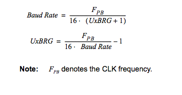
Atmega162 uart initialization, register values calculation formula.
|
Most important register in initializing Uart is UBRR. Its a 16 bit register. Divided in to two 8- bit registers UBRRL and UBRRH. In order to set the desired baud rate. We have to calculate the value for this register. The formula for calculating the value is given on right side. “Baud Rate” is the desired baud rate that we need. Fpb is the clock/crystal frequency on which the microcontroller is working. UxBRG is UBRR 16-bit register. After calculating the value, upload the higher 8-bits in UBRRH and lower 8-bits in UBRRL.
|
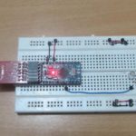
Atmega162 Serial Communication with MAX232(Rs232 Interface)

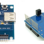
Atmega162 Serial Communication with FT232(USB to Uart Interface)
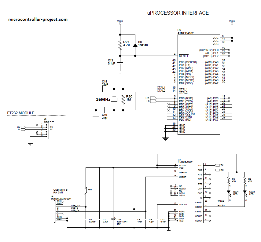
Atmega162 has 2 uarts 0 and 1. I am using uart-0 for this post. You can use the uart-1 if you want. Uart-0 is at pins#10,11 and Uart-1 is at pin#3,4. In the demo project i initialized the baud rate to 9600. I am sending my website name from atmega162 serial port to my pc(personal computer). For viewing the output on my computer i am using an putty.
A status led is connected to pin#25. It blinks after every second. Shows the program status, if the hardware is working or not. Note: The led is connected to pin#25 where as in code its declared as pin#22, its because for programming the pins are assigned different numbers. Remember the upper tutorial see that for more clarification.
Watch the Project Video Here.
Serial Communication using Uart of 8051(89c51,89c52) microcontroller
Serial Communication using Uart of Pic16f877 Microchip microcontroller
Serial data Transmission using 89c51 Communication
Serial rs485 communication between arduino uno and leonardo
Serial Communication using Atmega32A
Serial data received from pc using Microchip Pic Microcontroller
You may also like:


Filed Under: AVR, Electronic Projects

Questions related to this article?
👉Ask and discuss on EDAboard.com and Electro-Tech-Online.com forums.
Tell Us What You Think!!
You must be logged in to post a comment.