Overview
In today’s world, it is very common to use Arduino board to convert ideas into real applications. Generally we use Input/output pins of microcontrollers to implement the logic. What if we want to add the USB functionality in our projects? Yes, it is possible with Arduino boards like Micro/ProMicro or Leonardo. They can be used for building USB based applications. In this article we will use Atmega32u4 of Arduino Micro/ProMicro to build a simple HID (Human Interface Device) Mouse.
To understand the article and start building the application requires some prior knowledge on:
• Basic USB concepts
• Embedded C
• AVR microcontrollers
• WinAVR Studio
Understanding HID Mouse
We already know that during enumeration process, the Host requests the peripheral device for configuration information and the device responds with descriptors. This process helps in configuring and making the device recognizable at Host end. More detail information about descriptors and requests can be found in our previous articles on USB.
In Human Interface Device Class, there are two packets other than descriptors that are transmitted by HID device. They are Usage Report Descriptor and Data Input Report.
The Usage or Feature report contains the information related to the features of the device. For example, a mouse feature report generally contains information about number of buttons used, number of axis, scroll wheel, size of data report, minimum/maximum movement etc. The host can access this report by requesting the device using GET_REPORT request. This report is transmitted using Control Transfer. We will not go in detail of this report but some basic terms used in feature report that we need to understand are:
• USAGE_PAGE (BUTTON) – It declares the button feature of the mouse
• USAGE_MINIMUM (BUTTON1) – minimum number of buttons(1)
• USAGE_MAXIMUM (BUTTON) – maximum number of buttons(3)
• LOGICAL_MINIMUM (0) and LOGICAL_MAXIMUM (1) – it indicates that button status is represented by logical 0 and 1 bit
• REPORT_COUNT (3) – number of bits used for representing buttons(3)
• REPORT_SIZE (1) – one report of one byte for button feature
• INPUT (Data, Var, Abs) – it indicates that the button information will be send as variable data to computer
• USAGE_PAGE (GENERIC DESKTOP) – indicates the generic desktop feature like mouse movement
• USAGE (X) – indicates use of x axis in mouse movement
• USAGE (Y) – indicates use of y axis in mouse movement
• LOGICAL_MINIMUM (-1) and LOGICAL_MAXIMUM (+1) – indicates the increment in mouse movement in x and y axis. -1 for left or up movement and +1 for right and down movement
• INPUT (Data, Var, Abs) – it indicates that the coordinate information will be send to computer
• REPORT_COUNT (8) – eight bits for each axis
• REPORT_SIZE (2) – two reports, one for x axis and one for y axis.
There is also a PHYSICAL_MINIMUM and PHYSICAL_MAXIMUM associated with mouse movement. The LOGICAL and PHYSICAL movement information together helps in find the Resolution Multiplier for the mouse movement. The Resolution Multiplier is a scaler multiplier used to change the sensitivity. The resolution is calculated at the host end using the formula:
(Logical Maximum – Logical Minimum) / ((Physical Maximum – Physical Minimum)*10Unit Exponent)
For a 400 DPI mouse the Unit Exponent is -4.
The Data Report contains the data about the selected features. For example, the mouse data report may contain X axis increment, Y axis increment and button press information. This report is generally transmitted to the Host using Interrupt Transfer. Example of Data Report:
Bit7 Bit6 Bit5 Bit4 Bit3 Bit2 Bit1 Bit0
Byte0 Not used Not used Not used Not used Not used Middle
button Right button Left button
Byte1 X axis movement information as a signed integer
Byte2 Y axis movement information as a signed integer
Implementation
For implementing the USB HID Mouse we will use Arduino Pro Micro as it contains Atmega32U4 which is a USB AVR microcontroller. Some additional components that we require are:
• Breadboard
• Connecting wires
• Push buttons
• Micro USB cable
• 10K resistors
For building USB application we will need LUFA firmware. For more information on LUFA please refer our article on Prerequisite.
In the extracted LUFA zip file, we need to open Demos/Device/ClassDriver/Mouse folder. There will be some files in the Mouse folder like Mouse.c, Mouse.h, makefile, Descriptors.c, Descriptors.h
First we will modify the Mouse.h file. It can be done using any text editor like Notepad++.
Mouse.h
After opening the file we have to follow these steps:
• Comment the #include library statements for Joystick.h, LEDS.h, and Buttons.h ( We are commenting these libraries as we are not using any joystick, buttons board and LED board)
• Comment the #define statements for LEDMASK_USB_NOTREADY, LEDMASK_USB_ENUMERATING, LEDMASK_USB_READY, LEDMASK_USB_ERROR
Save the file with changes
Mouse.c
The following statements need to be commented in the file:
• In the main loop, comment the LEDs_SetAllLEDs()
• In SetupHardware() function, comment the Joystick_Init(), LEDs_Init(), Buttons_Init()
• In EVENT_USB_Device_Connect() function, comment the LEDs_SetAllLEDs()
• In EVENT_USB_Device_Disconnect() function, comment LEDs_SetAllLEDs()
• In EVENT_USB_Device_ConfigurationChanged() function, comment the LEDs_SetAllLEDs()
We have commented these statements because we are not using any LED board, Joystick or Button board with Atmega32u4.
In the main loop, we need to declare some input pins for push buttons that we will use for mouse controlling. Declare the PORTB as input port using DDRB = 0x00 and make all pins high using PORTB = 0xff. These statements need to implement in starting of the main. Be cautious; do not implement the statements after the infinite for loop. The below table indicate the pins at which buttons are connected:
Pin Function
PB4 Left Movement
PB5 Right Movement
PB6 Up Movement
PB2 Down Movement
PB1 Right Click
PB3 Left Click
ATMEGA32u4 as Mouse
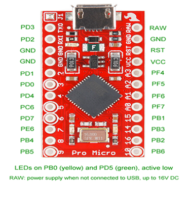
The pins need to be pulled up with a 10k resistor. The other end of the buttons needs to be grounded
The most important function that is used to create Mouse Data Report is CALLBACK_HID_Device_CreateHIDReport(). We will scan button input in this function and accordingly modify the data report. First we need to remove the statements for the Joystick and Button board that are not required.
These statements are:
• uint8_t JoyStatus_LCL
• uint8_t ButtonStatus_LCL
• All if conditions and their statements
Below is the snippet of the code that needs to be added in place of the removed statements:
if(!(PINB & _BV(PB4))) {
MouseReport->X = -1; // Move left in X
}
else if(!(PINB& _BV(PB5))) {
MouseReport->X = 1; // Move right in X
}
else
MouseReport->X = 0; // Do not move
if(!(PINB & _BV(PB6))) {
MouseReport->Y = -1; // Move up in Y
}
else if(!(PINB& _BV(PB2))) {
MouseReport->Y = 1; // Move down in Y
}
else
MouseReport->Y = 0; // Do not Move
if(!(PINB & _BV(PB3)))
MouseReport->Button = 1; // left mouse click
else if(!(PINB & _BV(PB1)))
MouseReport->Button = 2; // right mouse click
else
MouseReport->Button = 0; // no click
After modifying and saving the Mouse.c , we need to create Makefile for AVR-GCC compiler for compiling the Mouse.c
Makefile
In the Mouse folder there will be a make file that needs to be edited. The file can be edited using Notepad++. The following information needs to be edited:
• MCU = atmega32u4
• ARCH = AVR8
• BOARD = LEONARDO
• F_CPU = 16000000
Save the file and exit. Now all the files are edited completely for the basic HID Mouse application.
Compiling Mouse.c
For compiling the source code, we will use WinAVR Programmers Notepad. Please refer our article on Prerequisite for compiling process.
Burning Hex code
Please refer our article on Prerequisite for burning process.
After this open the Command Prompt, change the current directory to the directory containing the Hex file. This can be done using command: CD <address of the directory>.Now reset the Arduino and instantly run the command: avrdude -v -p atmega32u4 -c avr109 -P COM20 -b 57600 -D -Uflash:w:Mouse.hex:i after replacing the COM Port with the recognized one.
If the uploading process is successful, the Arduino will be shown as HID Mouse in the Device Manager. There is no need of installing any driver in the computer as we are using Generic HID Mouse. Use the buttons to test the functionality.
We can add an extra push button to add extra functionality in the device for Middle button click. For this, we just need to add logic in the firmware code.
Project Source Code
Project Source Code
###
//Program toif(!(PINB & _BV(PB4))) {
MouseReport->X = -1; // Move left in X
}
else if(!(PINB& _BV(PB5))) {
MouseReport->X = 1; // Move right in X
}
else
MouseReport->X = 0; // Do not move
if(!(PINB & _BV(PB6))) {
MouseReport->Y = -1; // Move up in Y
}
else if(!(PINB& _BV(PB2))) {
MouseReport->Y = 1; // Move down in Y
}
else
MouseReport->Y = 0; // Do not Move
if(!(PINB & _BV(PB3)))
MouseReport->Button = 1; // left mouse click
else if(!(PINB & _BV(PB1)))
MouseReport->Button = 2; // right mouse click
else
MouseReport->Button = 0; // no click
###
Filed Under: Electronic Projects

Questions related to this article?
👉Ask and discuss on EDAboard.com and Electro-Tech-Online.com forums.
Tell Us What You Think!!
You must be logged in to post a comment.