ATtiny85 microcontroller is a very popular 8-bit RISC microcontroller. It has become the first choice for professionals and developers because of its incredible features in such a small size. As its name suggests, it’s a tiny 8-pin (PDIP) microcontroller with almost all required features that any microcontroller should have such as built-in FLASH, EEPROM, SRAM, SPI, IIC, ADC, PWM, timer, comparator, IO, etc. We will discuss all of these in brief later, but before that, let us take a deep dive into the history of ATtiny microcontrollers.
History of ATtiny microcontrollers
ATtiny microcontrollers, also very popular as “TinyAVR,” were introduced by ATMEL in 1999. The idea was to introduce a comparatively small microcontroller (with fewer IO pins) without compromising the important microcontroller features. ATtiny microcontrollers have fewer IO pins, less program memory (also less data memory and SRAM), and comparatively limited and configurable inbuilt peripherals.
The first member of this family was ATtiny11. It was an 8 pin microcontroller with 1 KB of FLASH (program memory). Later that same year, new family members were added – ATtiny12 and ATtiny22. They were also 8-pin microcontrollers with built-in FLASH, EEPROM, and SRAM.
In 2002, ATMEL came up with ATtiny26, a fully loaded tiny microcontroller with 20 pins and 16 IO. It has 2 KB of FLASH, EEPROM, FLASH, built-in ADC, UART, SPI, IIC, PWM, and more on-chip. Later in 2005, they came up with the entire ATtiny24/44/84, and ATtiny25/45/85 microcontrollers. ATtiny24/44/84 are 14 pin microcontrollers with 12 IOs, and ATtiny25/45/85 are 8-pin microcontrollers with 6 IOs. They all are fully loaded with multi-functionality pins and features.
In 2016 ATtiny was acquired by Microchip Technology. Microchip has since developed and added many more family members in this series, such as the ATtiny202/204/402/404/804.
So this was a glimpse of ATtiny microcontroller history. Because this series is on the ATtiny85 microcontroller, we shall discuss limit our discussions to details around the ATtiny85 microcontroller.
ATtiny85 microcontroller
As mentioned earlier, ATtiny85 is 8-pin – 8bit AVR – RISC microcontroller. First, let’s start with its features.
ATtiny85 features:
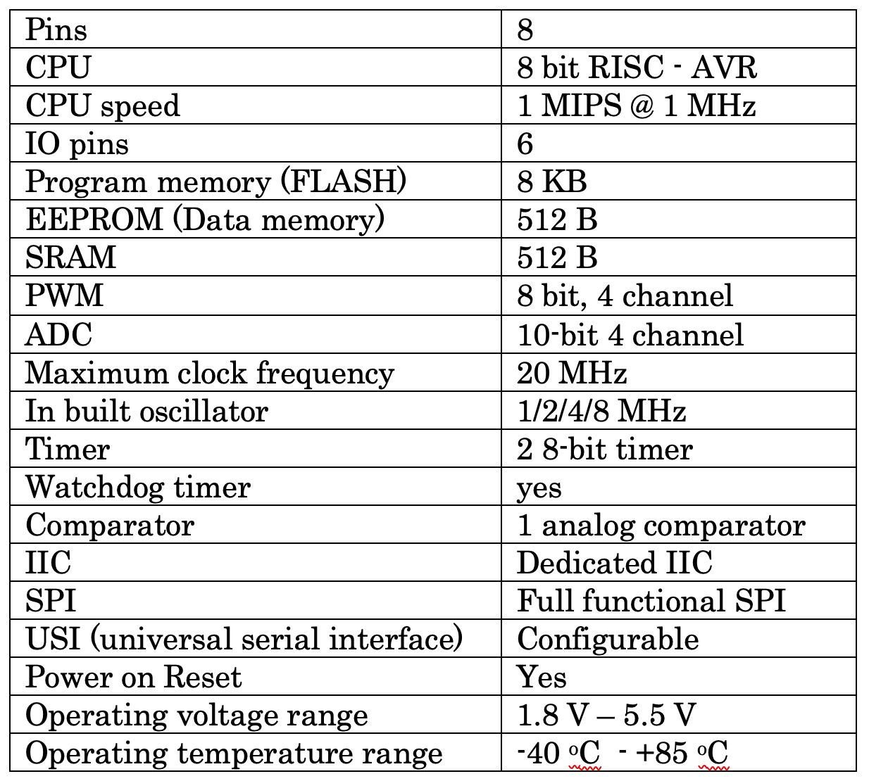
ATtiny85 inbuilt peripherals
IO Port/pins: ATtiny85 has a single bidirectional IO port – port B with 6 pins PB0 to PB5. All 6 pins can work as either input or output.
ADC: ATtiny85 has a 10-bit analog-to-digital converter with a multiplexer. It has four analog input channels where different analog sensors can be connected.
PWM: ATtiny85 has two 8-bit timers that can be used to generate PWM output. It has an 8-bit PWM with 4 output channels.
Timers: ATtiny85 has two 8-bit timers. They can work as a timer or a counter. A timer is used to generate time delay using a crystal clock / internal clock. The counter is used to count external events on external pins.
SPI: ATtiny85 has fully functioned 4 wire SPI with MOSI, MISO, SCK, and RESET pins. It is used to communicate with other uC, uP, sensor, or any peripheral device. Mostly it is used to program internal FLASH using an ICSP programmer.
IIC/I2C: It is also known as a two-wire interface because it needs only two wires 1) serial data – SDA and 2) serial clock – SCL. ATtiny85 has dedicated I2C pins to communicate with other I2C devices like I2C memory, I2C sensor, I2C, I2C clock, etc.
Memory: ATtiny85 has the following memory:
- FLASH – its program memory. It is where the program is stored. ATtiny has 8 KB of FLASH to store the program.
- EEPROM – its data memory. ATtiny85 has hardware architecture, so it has separate 512 bytes of EEPROM to store the data.
- SRAM – Attiny85 has 512 bytes of SRAM that can be used during program execution and temporary data storage. There are 32 GPR (general purpose registers) that can be used for this purpose.
ATtiny85 pin diagram and pin functions
ATtiny85 has a total of eight pins, and out of these eight pins, six pins have multiple functionalities, excluding two pins for Vcc and Gnd.
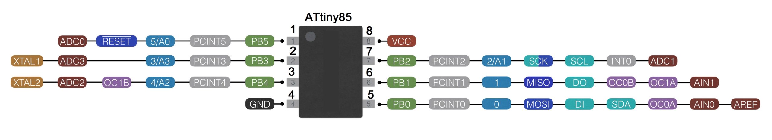
Pin 1: This pin has 4 different functions
- PB5 – it works as GPIO pin of PORTB pin 5.
- ADC0 – it is a channel 0 analog input pin for internal ADC
- RESET – it works as a reset input pin
- PCINT5 – its Pin Change is on Interrupt pin 5 and used as an interrupt input pin
Normally this pin is used as a reset input pin, and an active low pulse is applied to this pin to reset the microcontroller. To enable any of the above functionality, one has to set internal configuration bits.
Pin 2: This pin has 4 different functions
- PB3 – it works as GPIO pin of PORTB pin 3.
- ADC3 – it is a channel 3 analog input pin for internal ADC
- XTAL1 – it is used to connect an external crystal
- PCINT3 – its Pin Change on Interrupt pin 3 that is used as an interrupt input pin
Normally this pin can be used for digital input/output as pin 3 (PORTB pin 4), or else it can be used as analog input pin A3. So one can connect a digital/analog sensor or digital input/output device like LED or push button to this pin.
Pin 3: This pin has 5 different functions
- PB4 – it works as GPIO pin of PORTB pin 4.
- ADC2 – it is a channel 2 analog input pin for internal ADC
- XTAL2 – it is used to connect an external crystal
- PCINT4 – its Pin Change on Interrupt pin 4 that is used as an interrupt input pin
- OC1B – it is PWM output pin
This pin can be used as follows:
- Digital input/output pin as pin 4 (PORTB pin 4). One can connect a digital IO device like LED / push button or digital sensor with it
- PWM output pin 4. One can connect LED to vary its brightness or DC motor to vary its speed
- Analog input pin A2. One can connect an analog sensor with it
Pin 4: Ground pin. It is connected to circuit ground.
Pin 5: This pin has 7 different functions.
- PB0 – it works as GPIO pin of PORTB pin 0.
- MOSI – it is used as Master Out Slave In pin in SPI communication
- SDA – it is a Serial Data pin used in I2C interfacing for sending and receiving data
- PCINT1 – its Pin Change on Interrupt pin 1 that is used as an interrupt input pin
- OC0A – it is PWM output pin
- AIN0 – it is analog voltage input pin 0 for the internal comparator
- AREF – it is a reference voltage input pin for internal ADC
This pin can be used as the following:
- Digital input/output pin as pin 0. One can connect a digital IO device like LED / push button or digital sensor with it
- PWM output pin. One can connect LED to vary its brightness or DC motor to vary its speed
- analog voltage input pin
- data pin in I2C interfacing
- MOSI pin in SPI communication to communicate with a computer or other uC
Pin 6: This pin has the following five different functions:
- PB1 – it works as GPIO pin of PORTB pin 1.
- MISO – it is used as Master In Slave Output pin in SPI communication
- PCINT0 – its Pin Change on Interrupt pin 0 that is used as an interrupt input pin
- OC1A/OC0B – it is PWM output pin
- AIN1 – it is analog voltage input pin 1 for the internal comparator
This pin can be used as:
- Digital input/output pin as pin 1. One can connect a digital IO device like LED/push button or digital sensor with it
- PWM output pin. One can connect LED to vary its brightness or DC motor to vary its speed
- analog voltage input pin
- MISO pin in SPI communication to communicate with a computer or other uC
Pin 7: This pin has the following six different functions:
- PB2 – it works as GPIO pin of PORTB pin 2.
- SCK – it is used to provide serial clock signal in SPI communication
- PCINT2 – its Pin Change on Interrupt pin 2 that is used as an interrupt input pin
- ADC0 – it is a channel 1 analog input pin for internal ADC
- SCL – it is a Serial Clock pin used in I2C interfacing to provide a clock signal
- INT0 – it is external interrupt input pin 0
This pin can be used as:
- Digital input/output pin as pin 2. One can connect a digital IO device like LED / push button or digital sensor with it
- Analog input pin A1. One can connect an analog sensor with it
- External interrupt input pin
- serial clock in SPI and I2C communication
Pin 8: Vcc pin. This pin is connected with a 5 V supply.
This tutorial explored the pin functions of the ATtiny85 microcontroller. As you can see, all six pins of the ATtiny85 microcontroller have four to seven multiple functions. That means the same pin can be used for different purposes as per the requirement of the application.
Now, as you are more familiar with ATtiny85, its pins, pin functions, etc., our next tutorial will discuss how to work with ATtiny85, including how to program it and use it in our application.
You may also like:

Filed Under: AVR., Featured Contributions, RISC microcontroller

Questions related to this article?
👉Ask and discuss on Electro-Tech-Online.com and EDAboard.com forums.
Tell Us What You Think!!
You must be logged in to post a comment.