In the previous tutorial of this series, we have seen how to work with ATtiny85, how to program it, and also we have built our first – hello world application – that is LED blinking application using ATtiny85.
So let us extend it to the next step – means one step advance. We shall connect 5 LEDs with 5 port pins of ATtiny85 and generate different chasing effects. Five different color LEDs are connected with ATtiny85, and it will blink them in a different pattern at a different rate that will create eye-catching multicolor chasing effects. So let’s see how to do this.
If you are not following this tutorial series from the beginning, you are requested to go through the following two tutorials that explain and demonstrate how to work with ATtiny85 and step by step guide to build a hello world (LED blinking) application.
How to work with ATtiny85
LED blinking using ATtiny85
Circuit diagram
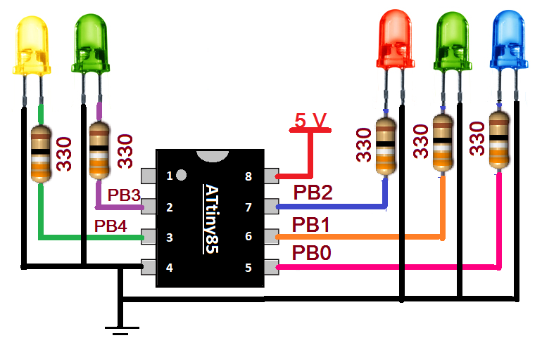
Circuit connections
As you can see, 5 different color LEDs are connected with 5 port pins of ATtiny85. The anodes of LEDs are connected with PORTB pins PB0 (pin 5), PB1 (pin 6), PB2 (pin 7), PB3 (pin 2), PB4 (pin 3) through current limiting 330Ω resistors. All cathodes of LED are connected to pin 4 that is the Gnd pin. A 5 V supply is connected to a Vcc pin (8)
Program
The program is written in Arduino IDE software using C programming language. It is compiled, and a HEX file is created that is downloaded into the internal FLASH of ATtiny85.
Program logic
Program logic is straightforward. The program generates 3 different chasing effects. Each effect runs for 50-60 sec (approx 1 min) and repeats one after other continuously like effect1 – effect2 – effect3 – effect1 – effect2 – …..
The first effect is the simplest one. Each LED blinks in sequence from led1 to led 5.
In the second effect, one by one, all LEDs are turned ON from led1 to led5, and then all are turned OFF in reverse sequence from led5 to led1.
In the third effect, alternate LED turns ON and OFF means led1-led3-led5 are ON and led2-led4 are OFF, then after delay led1-led3-led5 are turned OFF, and led2-led4 are turned ON.
In the next tutorial, we shall learn to vary the brightness of the LED.
You may also like:


Filed Under: Tutorials

Questions related to this article?
👉Ask and discuss on EDAboard.com and Electro-Tech-Online.com forums.
Tell Us What You Think!!
You must be logged in to post a comment.