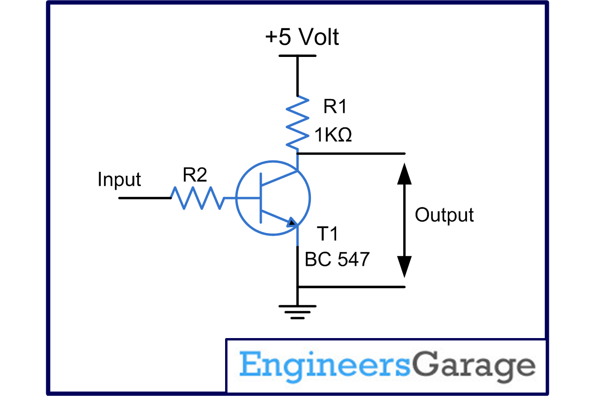
The microphone converts the mechanical vibrations into electrical signals but the amplitude of these signals is not enough to drive a speaker. In this project, these signals are amplified before connecting to the speaker.
Facts about the type of transistor used in the circuit:
1. This circuit is based around transistor BC 547, an NPN transistor.
2. Providing a maximum gain of 800, this transistor is widely used in amplification and switching circuits.
3. The transistor shows highly stable working at quiescent point (Q-point) once properly biased using a DC source.
In this project, the output from the microphone (mic) is fed to the base of Transistor T1 (BC 547) which acts as a class B amplifier. When the input signal increases towards positive peak, the base of T1 gets more and more forward bias. At the same time the collector current also increases. Due to this the voltage drop across resistor R1 (1k ) rises and consequently the output goes on decreasing. When the signal drops towards the negative peak, the forward bias on the base of T1 goes on falling along with the collector current. Hence the voltage drop across the resistor R1 also falls and the output also goes on increasing. Also note that the output is 180
 out of phase with respect to the input, i.e., when the input increases the output decreases and vice versa. The Resistor R2 is used to check the base current of T1.
Circuit Diagrams
Project Components
Filed Under: Electronic Projects


Questions related to this article?
👉Ask and discuss on Electro-Tech-Online.com and EDAboard.com forums.
Tell Us What You Think!!
You must be logged in to post a comment.