In the previous tutorial, we learned how to design an audio equalizer. Here, we’ll cover how to design an audio mixer. An audio mixer is an electronic device that processes, combines, and modifies audio signals in digital or analog form. Typically, it has a separate volume knob for each source, including the input and output.
Analog and digital signals can be combined by different types of audio mixers. In digital form, analog audio signals are encoded so that the information within the signal becomes independent of the amplitude of the signal. Digital signal processing techniques are used to combine the analog audio signals and, typically, an operational amplifier (op-amp) is used.

A two-channel audio mixer.
For this project, we’ll design a two-channel audio mixer, which combines two signals into one. One of the audio sources will be taken from a smartphone and the other will be from a microphone. The microphone’s audio will be amplified to line level by a pre-amplifier before it’s combined with the smartphone’s audio using an op-amp circuit.
The combined audio will, then, be played on a speaker. So, for example, one will be able to mix vocals with an audio track when using this mixer. It can be used for audio recording, concerts, DJ-related work, and for public announcements.
A pre-amplifier and power amplifier are the main building blocks of the circuit. We’ll be using some common terms associated with audio amplifiers and filters, which are covered here.
Components required


Circuit connections
The audio mixer combines two or more audio signals by using a summer, which mixes multiple input signals together. These mixed signals are, then, amplified via a power amplifier at the output for a combined sound.
This audio mixer circuit is built by assembling the following components:
Power supply – The pre-amp for the microphone requires a 5V DC and the power amplifier is powered by a 9V DC in the circuit.
Smartphone – To receive audio from the smartphone, a 3.5 mm audio jack must be plugged into it. The jack should have three wires: one to ground, one for the left channel, and a third for the right channel. In this circuit, only one of the channels is used as an audio source. The ground wire of the jack is connected to the common ground of the circuit.

A 3.5mm audio jack.
Volume control – To control the volume input through the smartphone, a variable resistor (“RV1” in the circuit diagram) is connected between the audio jack and the power amplifier. By adjusting this resistor, it’s possible to adjust the smartphone’s volume.
Microphone – An electret microphone, a type of electrostatic capacitor-based mic, is used as the input source for the second audio signal (as there are two). It requires a biasing voltage between 1 to 5V to power the inbuilt FET buffer, which has an extremely high input resistance and a low output resistance.
Typically, this microphone is powered by 1 V to 5 V DC through a resistor with a value between 1K to 10K ohms. So, there must be sufficient voltage at the bias pin of the microphone so it could obtain the audio signal.

An electret microphone.
 In the circuit diagram, a resistive divider network (“R1” and “R2” in the circuit diagram) is used to ensure the microphone has a fixed voltage. A 10 uF capacitor (“C1”) is connected at the resistor’s junction point, which helps maintain the voltage for one of the microphone’s pins (the other is connected to the common ground). You can learn more about microphones here.

MAX4468 IC


A pin diagram of the MAX4468 IC.
For this project, the IC is used as an inverting amplifier, which has negative feedback. This makes it a better choice than a non-inverting amplifier. This is because the inverting amplifier changes the phase of the output (the signal amplitude) by 180 degrees with the input (the signal amplitude).
However, this phase inversion does not affect the audio signal as humans will only respond to the intensity of the sound. The intensity is the energy flowing through an area in a given time, expressed in joule/s/m2. The energy of the wave is proportional to the square of its amplitude.
So, for a unit area, the intensity is also proportional to the square of the amplitude.
I A2
You’ll note that changing the sign of wave has no effect on I.
How it works:
- To provide the DC bias to the amplifier’s non-inverting pin, a 0.01-uF capacitor (“C3”) is connected along with a resistor divider network at the IC’s pin 3.
- A 0.1-uF capacitor (“C2”) is connected at the IC’s inverting input pin to provide the decoupling of the AC signal from the DC.
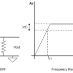
- A 47-pF capacitor (“C4”) alters the frequency response of the amplifier and, at high frequency, acts as a short circuit, allowing the signal to bypass through the R2 resistor. This means the gain of the amplifier is reduced when at high frequency. And, when at low frequency, this capacitor acts as an open circuit, so it does not affect the gain. Essentially, it serves as a high-pass filter in the circuit.
The typical application circuit (as per the MAX4468’s data sheet) is used for designing the pre-amplifier.
The line output is drawn from the IC’s pin 8.

The circuit diagram of the MAX4468 IC-based microphone audio pre-amplifier.

A profile of the MAX4468 IC-based microphone audio pre-amplifier.
Volume control – To control the volume input through the microphone, a variable resistor (“RV2”) must be connected between the pre-amp output pin and the power amplifier. By adjusting this resistor, the microphone’s volume can be adjusted.
Summer and the LM386 power amplifier – The two audio sources (the microphone and audio track) require a summer for mixing. The LM386 IC will serve as the summer and power amplifier.
The LM386 is a low-voltage audio power amplifier IC, which operates at a voltage ranging from 4 to 12 V. In this circuit, the IC receives a bias voltage of 9 V. The IC can drive a load with an impedance ranging from 4 to 32 ohms, which is well-suited to the output speaker as it has 8 ohms of impedance.
Internally, the voltage gain of the IC is set to 20 (26 dB) but it can be set between 20 (26 dB) to 200 (46 dB) by connecting a suitable combination of resistor and capacitor between its pins 1 and 8.
The IC has 8 pins in a PDIP package with the following configurations:


The LM386 IC pin diagram.
 Its internal circuitry can be represented by this functional diagram:
This IC is an operational amplifier with a voltage gain that can be adjusted by using a proper RC circuit between its gain setting pins. With the gain setting pins open, the voltage gain of the amplifier can be internally set to 20 (26 dB) and the gain of the amplifier will be 20.

LM-386 IC
Here’s what you need to know about the setup of the pins:
- Pin 2 is the inverting input pin, which is grounded.
- Pin 3 is the non-inverting input pin that feeds the audio signal from both sources.
- A 100-uF filter capacitor (“C7”) is used to remove any high-frequency ripples at the input.
- Pin 4 is the ground pin, which is connected to the common ground.
- Pin 5 is the IC’s output pin and it’s connected to a 1000-uF capacitor (“C11”) to block any DC components. The DC components (as are appeared in case of clipping effect) can damage the speaker connected at the output of the circuit.
- Pin 6 is the IC’s power supply pin and it’s connected to 9V of DC.
- An RC filter circuit consisting of a 10-ohm resistor (“R7”) and a 0.05-uF capacitor (“C10”) is used at the output pin. This is called a Zobel network, which ensures the impedance of speaker by stabilizing the frequency and oscillations at the output. If the C10 capacitor and R7 resistor were swapped, it would be no longer a Zobel network, but the output impedance would still remain constant.
- Pin 7, the bypass terminal pin, is grounded using a capacitor to improve the stability of the amplifier output.

The circuit diagram of a 1-watt audio power amplifier.
The amplifier circuit should look like this:

The LM386 is also used to choose the output power of the mixer circuit. For this project, it will provide a power of approximately 700 mW for a load of 8 E at a supply voltage of 9V.
Speakers – A speaker with a 10-watt power rating and 8 ohms of impedance is used as the load at the output of the amplifier. The speaker is connected at the IC’s pin 5, which is also the LM386’s output pin. The ground wire of the speaker is connected to the common ground.
Since the output power of the circuit is about 1 watt, so, a speaker with a minimum of 1 watt or greater should be used. Here, we used an 8E 10-watt speaker. A variable resistor (“RV3”) is connected before the speaker to adjust its output volume.
You can learn more about speakers here.
Safety first
When assembling this circuit, follow these precautions…
1. Always use the filtering capacitor at the power supply’s input terminal to avoid unwanted ripples.
2. Select a speaker that’s equal to or of a high power-rating as the amplifier’s output power.
3. Use a series capacitor at the output of the amplifier to block any DC components.
4. Employ the Zobel network for frequency stability.
5. Calculate the maximum power rating of the amplifier before connecting it to the speaker. The practical value may differ from a theoretical one.
6. Double-check the power rating of LM386 IC by referring to its data sheet, as different companies have different ratings.
7. Avoid clipping the output signal as it may damage the speaker.
8. Place the components as close as possible to one another to reduce the noise in the circuit.
How the circuit works
This mixer circuit receives audio from two different sources: a smartphone and a microphone. A MAX4468 pre-amp is used to amplify the audio input from the microphone to line level before directing it to the power amplifier.
The audio from both sources is fed to the power amplifier IC’s non-inverting pin. The amplifier also works as summer and combines the two audio signals. The audio waveforms from the microphone, audio jack, and power amplifier output pin can be observed by connecting CRO probes.
The audio waveform from the microphone is:
 The audio waveform from the smartphone is:

The mixed waveform from the power amplifier is:

You may also like:


Filed Under: Audio, Tutorials

Questions related to this article?
👉Ask and discuss on EDAboard.com and Electro-Tech-Online.com forums.
Tell Us What You Think!!
You must be logged in to post a comment.