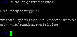
In this particular project Ubuntu is installed on Raspberry pi board and is loaded on the Raspberry pi board and is connected to a router using a cross-over LAN cable. Hence the only additional hardware required with the Raspberry pi for this project is a LAN cable only.Once connected to the router with Ubuntu OS on it, it can be accessed remotely from other systems connected in same LAN network. The board can be accessed from a Linux PC using the secure shell which is enabled in the Ubuntu of Raspberry pi board.This article focus on how to configure the Raspberry pi board as a web server and the technique to make it serve a graphical game for those who type the IP or address of the Raspberry pi board from the address tab of their web browser. The Raspberry pi web server is available in the same LAN network or it can be made available to anyone who has the internet connectivity using the technique of port forwarding.
How to Add Sound to Raspberry Pi Game Pad- (Part 37/38)
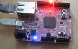
The gamepad is a simple circuit built on a breadboard with few buttons, LEDs and a resistor array. There are eight general purpose IO pins on the 13*2 pin connectors of the Raspberrypi board and among them four pins has been selected as input and then remaining four pins as output. The input pins are connected to push button and are pulled down using 1K resistors. The output pins are connected to the LEDs through another set of 1K resistors. For this project the Raspberry pi board is loaded with Ubuntu and is remotely accessed using VNC. To access the pins that coming out of the Broadcom controller the C library “bcm2835” has been downloaded and installed. This article focuses on how to add sound to a game that is coded to be played with a Raspberry pi gamepad.
Simple Raspberry Pi Game Pad for Ball Catching Game – (Part 36/38)
Raspberry Pi is provided with a RCA connector which can be used to connect it directly to a TV screen which is based on PAL and NTSC standard. The board also has a HDMI connector output which can be used to connect the board to a HD TV. One can also use remote login to access the Raspberry pi and view the GUI (Text User Interface) on the PC screen. The Raspberry pi board is also very easy to interface with external devices or circuits through its pin outs. This makes the Raspberry pi a suitable platform for playing and developing interesting games.This article discusses how to develop a simple graphical game using the HTML5 and JavaScript language and to interface it with an external custom made game pad hardware connected to the pins of Raspberry pi board.
Playing Snake Game using Raspberry Pi Game Pad- (Part 38/38)
This article discusses about how to develop simple game pad hardware and interface it with the Raspberrypi board and also about the technique of interfacing a game code written in HTML5 with the game pad. Here a Snake game written in HTML5 and JavaScript is modified in such a way that it can be played with the new game pad having four push buttons. In this project the techniques of signals, pipe, fork etc. are used get the game running. The Snake game running on a browser window forms the GUI or front end of the entire system. In a Linux operating system each hardware device is represented as a file. In this project there is game pad which is the hardware and there is a process which reads from the game pad and there is also a Pipe file or FIFO in-between the game and the game pad reading process.
Controlling Hardware using GUI in Raspberry Pi -(Part 32/38)
The Graphical User Interface (GUI) helps the user to communicate with the system effortlessly. The GUI is considered as the front end of an application. In a Linux operating system each hardware device is represented as a file. The device can be controlled by simply reading and writing into that file. The hardware of an operating system is on the one side and the user trying to access the hardware is on the other side, and in between them there might be several layers of process running which communicates each other using inter process communication methods. The GUI is the process which the user can use to communicate with all these process layers and finally communicate with the Hardware. This project demonstrates how to create a GUI using the QT which can control the LEDs connected to the Raspberrypi board.
How to Control Hardware using Named Pipe – (Part 34/38)
In a Linux operating system all each hardware device is represented as a file. The device can be controlled by simply reading and writing into that file. The hardware of an operating system is on the one side and the user trying to access the hardware is on the other side, and in between them there might be several layers of applications running which communicates each other using inter process communication methods. This project demonstrates how to control a process which can turn on and off the LEDs of the Raspberrypi with the help of another process by writing into a pipe file. The Raspberrypi is a mini computer which can be used to learn and experiment the concept and working of an Operating System. The Raspberry pi is a device which uses the Broadcom controller chip which is a SoC (System on Chip). This SoC has the ARM11 processor which runs on 700 MHz at its core.
Voice Record and Playback from SD Card Using GR Sakura
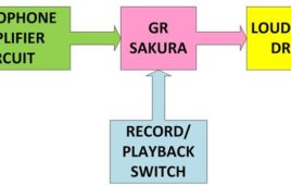
There are so many devices available which can record and playback voice. Most of the digital devices like mobile phones can use the SD card to record the voice signals and playback. This project demonstrates how to record voice signals on a micro SD card and play it back using the GR SAKURA board. Voice signals are continuous analog signals and the digital devices like microcontrollers cannot handle the continuous analog signals. Most of the microcontrollers have an ADC module which can do analog to digital conversion. The microcontroller uses sampling technique to convert the continuous analog signals to discrete digital equivalent samples. While recording the voice, the GR SAKURA board samples the voice signals and writes the sampled values to a file at the sampling time itself. The same file is opened again and reads the values at the same frequency at which they are sampled.
Talking Parrot using GR Sakura

This is a very interesting and funny project made with the help of the GR SAKURA board which can record the speech and play it back in the voice of a parrot. It might look like a toy but there are lot of technology behind its working like voice sampling, memory card interfacing, PWM etc. Voice signals are continuous analog signals and the digital devices like microcontrollers cannot handle the continuous analog signals. Most of the microcontrollers have an ADC module which can do analog to digital conversion. The microcontroller uses sampling technique to convert the continuous analog signals to discrete digital equivalent samples. While recording the voice, the GR SAKURA board samples the voice signals and writes the sampled values to a file at the sampling time itself.
Voice Sampling and PWM Reproduction by GR Sakura
Voice signals are continuous analog signals and the analog circuits or systems can only handle the voice signals without changing their continuity feature. There come situations in which the analog voice signals need to be applied as the input to simple digital microcontrollers. The digital devices like microcontrollers cannot handle the continuous analog signals. Most of the microcontrollers have an ADC module which can do analog to digital conversion. The microcontroller uses sampling technique to convert the continuous analog signals to discrete digital equivalent samples. The digital microcontrollers based devices cannot produce analog output also, since their output will be always either logic high or logic low. To generate the effect of the continuous analog signal at any output device connected to the microcontroller, they use a technique called PWM (Pulse Width Modulation). In this project the sampling and reproduction of voice signal is demonstrated with the help of GR SAKURA board.
How To Save A Text In The EEPROM Of The Arduino- (Part 21/49)
A microcontroller might need to store its data like sensor value, or a particular count or image data for a long period of time. The most common type of memory used with the microcontroller based systems is EEPROM. The EEPROM stands for Electrically Erasable Programmable Read Only Memory which is a kind of Read Only Memory (ROM), which can be written and erased by means of electrically programming and hence the name. Once programmed the data it will remain in the memory for a very long time even if there is no power available. EEPROM memory is widely used in microcontroller systems where some particular data need to be retained each time the system is turned on and to save particular data before the system is powered off.here are several EEPROM memory chips available which can be interfaced in a microcontroller based system with the help of serial communication protocols.
How to Get GUI on Raspberry Pi – (Part 04/38)
The Raspberry pi is a single board minicomputer which comes without input and output units, but with connectors for them. The board is designed to be easy to use and available at the least possible price. The main intention of releasing such a board is to provide computer education to the remote schools where the PCs are not very commonly used. The idea is to use the TV screen as the display unit for the Raspberry pi board and hence converting the TV into a computer. The board is hence provided with a RCA connector which can be used to connect it directly to a TV screen which is based on PAL and NTSC standard. The board also has a HDMI connector output which can be used to connect the board to a HD TV, but there is no VGA connector.
Named Pipe Example Using Raspberry Pi – (Part 33/38)
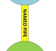
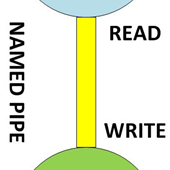
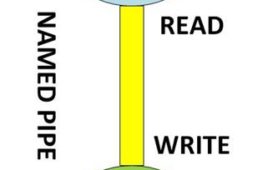
Multi-tasking Operating Systems can run several processes at a time creating and effect of parallel processing with the help of the high speed processor. There are different kinds of Inter Process Communication (IPC) system and the Named Pipe is one of the simplest of them. The Named Pipe is actually a temporary file having a particular name and stored at a particular directory whose name and location are known to the processes which needs to communicate with each other. The Named Pipe is also called First In First Out (FIFO).This project demonstrates how two programs communicate each other using named pipe. In this project a simple program is written which creates a pipe and continuously checks for any data on the pipe. The data is written to the pipe by simply using terminal commands. As soon data appears on the pipe, the program reads it and prints back on the terminal.
Remote Home Automation Using GR Sakura
This project uses the Renesas microcontroller based development board called GR Sakura. Detailed here is the method of enabling the Ethernet module of the Sakura board, how to configure it as a server and also how to control them using a web page provided by the Sakura board for those who tries to connect with the board using an internet enabled PC, mobile phones etc. The LM35 temperature sensor is connected with the board for sensing the temperature and turning on/off the lights are demonstrated by the LEDs connected to the I/O port which can be easily replaced by a light driving circuit or relay. The demonstration of a small remote home automation system is done which can be used to control two lights and read temperature of a room from anywhere around the world using internet enabled devices.
How to Create Buttons in Qt- (Part 31/38)
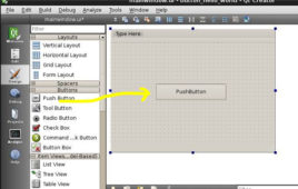
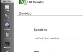
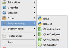
In this project the Raspberrypi board is loaded with Ubuntu and is remotely accessed using VNC. The Raspberrypi board is also connected to the internet. Downloading and installing the fourth version, QT4 using commands are already discussed in a previous article. There is another article which discusses about how to start with programming in QT, a hello world program using QT. Once the installation is complete the user can find them listed under the installed programs for ‘Programming’. The list includes “Qt 4 Assistant”, “Qt 4 Designer”, “Qt 4 Linguist” and “Qt Creator”. The “Qt 4 Assistant” is basically provides help in the form of documentations related to the topics in QT. “Qt 4 Designer” is where the user can create a design and save it as a ‘.ui’ file which can then be used in QT projects. The “Qt 4 Linguist” provides a language view of the design created.
Hello World Program using Qt in Raspberry Pi- (Part 30/38)
The Raspberrypi board is powerful enough to run large operating systems like Linux, Mac and Windows. Linux operating systems especially Ubuntu is preferred for all kind of programming and development.The board is provided with a RCA connector which can be used to connect it directly to a TV screen which is based on PAL and NTSC standard. The board also has a HDMI connector output which can be used to connect the board to a HD TV. A board capable of generating graphics on standard display screen needs a perfect application using which the programmers can exploit that capability. The ‘QT’ is a widely used platform for creating GUIs in Linux environment.Qt is an application which helps indeveloping the UI framework using the Qt IDE. Qt uses standard C++ but it also supports support many compilers, including the GCC C++ compiler and the Visual Studio suite.
How to Install Qt in Raspberry Pi- (Part 29/38)
The Raspberry pi is a device which uses the Broadcom controller chip which is a SoC (System on Chip). Raspberrypi is provided with a RCA connector which can be used to connect it directly to a TV screen which is based on PAL and NTSC standard. The board also has a HDMI connector output which can be used to connect the board to a HD TV. A board capable of generating graphics on standard display screen needs a perfect application using which the programmers can exploit that capability. The ‘QT’ is a widely used platform for creating GUIs in Linux environment. Qt is an application which helps indeveloping the UI framework using the Qt IDE. Qt uses standard C++ but it also supports support many compilers, including the GCC C++ compiler and the Visual Studio suite.This article explains how to install the QT in Raspberrypi.
How to Use Signal Values and Messages to Read Multiple Inputs- (Part 27/38)

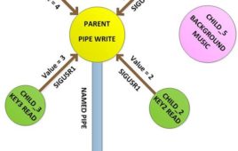
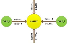
In this particular project a Parent creates only one Childs process which will then create its own Child Processes. The Grand Child Processes of the Parent processes are then used to read the status of the four input pins independently. The Child processes are made to send a signal ‘SIGUSR1’ to their own Parent process whenever the status of the input pin changes. Each Child process sends a different value along with the signals they sent. As soon as their Parent process receives a signal, it reads the value from the signal and sends the status in the form of a message along with a signal to the original Parent process. This forms a Process System made up of 4 Grand Child process, a Child Process and a Parent process where the Parent is free to do its work, but the Child can get the attention of the Parent by sending signal.
How to Read Multiple Inputs using Signal Values-(Part 10/38)
Multi-tasking Operating Systems can run several processes at a time creating and effect of parallel processing with the help of the high speed processor. The Linux Operating Systems provides Multi-User-Multitasking. Linux operating systems especially Ubuntu is preferred for all kind of programming and development. In a multi-tasking environment of the Operating System several processes executes at the same time and the Signals provide an Inter-Process Communication (IPC) method. The Operating System sends signals to the process to notify them about the events occurred along with passing a value or message. The Raspberrypi is a mini-computer board which is powerful enough to run large operating systems like Linux, Mac and Windows. The Linux operating systems like Archlinux ARM, OpenELEC, Pidora, Raspbmc, RISC OS and the Raspbian and also Ubuntu versions are available for the Raspberrypi board. The device which uses the Broadcom controller chip which is a SoC (System on Chip).
How to Send Message between Processes using Signal in Raspberry Pi (Part 25/38)
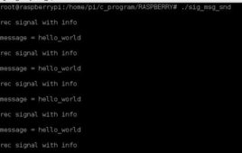
In a multi-tasking environment of the Operating System several processes executes at the same time and the Signals provide an Inter-Process Communication (IPC) method. The Operating System sends signals to the process to notify them about the events occurred and to control them. A Parent process can create another process, which are called the Child process and the Parent process can use signals to control the Child process. The Child can also send a signal back to the Parent process.The signal is also a means of passing message between independent processes. A signal Handler function inside the process will always get the signal number of the received signals. The Signal Handler function can be set up in such a way that it can receive value or messaged passed along with the signals by the other processes. This article discusses how to send a message along with a signal from one process to another.
How to Send Value Between Processes Using Signal -(Part 24/38)
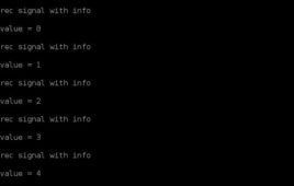
Linux operating systems especially Ubuntu is preferred for all kind of programming and development. In a multi-tasking environment of the Operating System several processes executes at the same time and the Signals provide an Inter-Process Communication (IPC) method. The Operating System sends signals to the process to notify them about the events occurred and to control them. A Parent process can create another process, which are called the Child process and the Parent process can use signals to control the Child process.The Raspberrypi is a board actually designed for helping computer education for remote schools but it is a good platform for programmers especially beginners to explore various coding techniques. The Raspberrypi is a mini-computer board which is powerful enough to run large operating systems like Linux, Mac and Windows. The Linux operating systems like Archlinux ARM, OpenELEC, Pidora, Raspbmc, RISC OS and the Raspbian.