RGB bulb means bulb made up of three LEDs – RED, GREEN and BLUE. It generates light of many different colours. As we all know RED, GREEN and BLUE are three primary colours and all other colours can be generated by mixing these 3 colours in different amount. So in RGB bulb the intensity of RED, GREEN and BLUE LEDs are varied – means the amount of RED, GREEN and BLUE colours are varied to generate different colour or shade of different colour.The intensity of LED is varied using PWM generated by NE555 IC. NE555 chip generates PWM when it is connected in astable mode. So three NE555 ICs are used to vary the intensity of three LEDs – RED, GREEN and BLUE.
FOC Light Fountain with RGB Colour Control

Here I am presenting very interesting project that can be use as a nice show piece or display item with live colours. The desire colour can be set manually from 7 different RGB (Red-Green-Blue) colour combinations. FOC light fountain is a made up of hair like small optical fibre cables bunched togather at one side. When light of different colours is given from that side the entire bunch of fibers look like fountain of light. Such show pieces are readily and easily available in gift article shops or show piece item shops.
Designing a servo motor angle controller using IC NE555

The article discusses designing a servo motor angle controller using the IC NE555. The servo motor used here for an experiment is an 11-gram micro servo motor with the following specifications. Rotational range 160o Operating voltage …
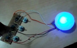
Color generation using RGB LED, Arduino, and potentiometer
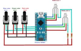
RGB LED is a combination of three LEDs red-green-blue together. It has four terminals – either anode or cathode, and the other three are for these three colors. Interestingly, when two colors inside the LED are turned ON simultaneously, the LED gives a different color. Also, as the amount or intensity of any color in…
Arduino-based multicolour LED chaser
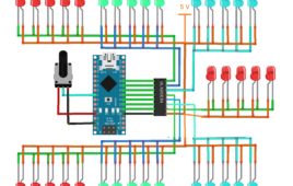
If you search on Google or youtube for LED chasers, you will find quite a bit of LED chasers. And here also, by just looking at the title, you will say, “one more LED chaser!!!!… Oh, No, please!!!!” But wait, wait, wait. This is somewhat different. Most of the LED chasers are of single colour…
ATtiny85 microcontroller tutorials, Part 5: LED intensity control using ATtiny85

In the previous tutorials in this series, we have seen how to generate different chasing effects by blinking LEDs. So we were simply turning the LED ON and OFF. In this tutorial, we shall vary the brightness (intensity) of LED. We shall use the PWM output of ATtiny85 to do this. So let’s see how…
ATtiny85 microcontroller tutorials, Part 6: LED intensity control using potentiometer and ATtiny85

In previous tutorials of this series, we saw how to vary the intensity (brightness) of LEDs using the PWM output of ATtiny85. This tutorial shall take it to the next step by varying LED brightness using a potentiometer (pot). The pot will give an analog output of 0 to 5V. ATtiny85 has an inbuilt ADC…
Tutorial 7: DC motor speed control using ATtiny85

In the previous two tutorials of this series, we have seen how to vary the intensity (brightness) of LEDs using the PWM output of ATtiny85. In this tutorial, we shall use a PWM output to vary the speed of a DC motor. DC Motor speed varies as the potentiometer is varied. As we have learned…
Tutorial 8: RGB LED interfacing with ATtiny85
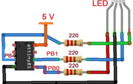
In the previous three tutorials of this series, we saw how to vary the intensity (brightness) of LED and DC motor speed using the PWM output of ATtiny85. In all those previous tutorials, we used only one PWM output, but now we shall simultaneously use three PWM outputs of ATtiny85. ATtiny85 has three PWM outputs…
Tutorial 9: Device control using smart phone’s Bluetooth and ATtiny85

In this tutorial series, we have learned about interfacing potentiometer to get analog input, interfacing of RGB LED by generating PWM output, DC Motor speed control using PWM output, and some other things. This tutorial explains the serial communication of ATtiny85 with Bluetooth module HC05. ATtiny85 does not have built-in UART or USART with Rx…
Tutorial 10: Wireless sensor data transmitter using Bluetooth and ATtiny85
In the previous tutorial, we have learned how ATtiny85 serially communicates with Bluetooth module HC05 and send/receive commands from smartphone Bluetooth This tutorial also involves the role Bluetooth module HC05. But instead of receiving commands from a smartphone, it sends sensor data values to the smartphone. The sensor is connected to an analog input pin…
ATtiny85 microcontroller tutorials, Part 3: Building LED blinking application using ATtiny85
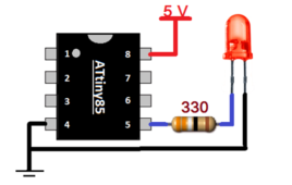
In the previous tutorial, we learned we need the following hardware and software tools to build any application using ATtiny85. Arduino IDE software USB SPI AVR programmer PROGISP software So let us build the first LED blinking, “hello world” application for the ATtiny85 microcontroller. Open Arduino IDE. Open LED blinking example from file->example->basic->blink Modify the…
Computerized Pick n Place Robot
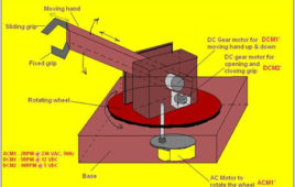
Complete robot is combination of three subsections: Robotic mechanism, Hardware driver circuit, controlling software in VC++.Obviously, the main part will be the mechanism that actually forms the body of robot means moving hand that picks or places any object. Function of hardware driver circuit is to drive all three motors and actuates all the motions of robot. Controlling software is also an important part of this robot because it will take care of all controlling actions. The main functions of this section are: Rotate the hand to one specific angle from where the object should be picked or to be placed, Move the hand up or down to pick or place the object, and Open or close the grip of hand depending upon size of object.
Working with Universal Microprocessor Simulator (UMPS)

UMPS is perhaps most efficient virtual simulator for simulating the programs of 8051/52/2051/4051, PIC micro controllers, HC micro controllers, AVR microcontrollers etc. It provides perfect platform for simulating real time applications. It has wide varieties of peripherals to connect with micro-controllers like in display there are LED, matrix LED, alpha numeric display, all type of LCD etc. Other peripherals like ADC, DAC, serial transmitter-receiver, function generator, I2C memory, I2C display, PWM converter, digital recorder and player, shift register etc. are given to design any embedded system. With the help of umps, one can create virtual 8051 training board on his computer’s desktop. He can simulate all kind of programs by connecting required resources like 7 segment display, Matrix LED, LCD, Matrix keyboard and all he wants.
4 Channel Programmable FM Remote Control

This is programmable FM remote control can be used for some specific applications. Phase Lock Loop (PLL) IC-567 is used in transmitter and receiver part as oscillator and filter respectively. It can operate/control any device / application from the distance of around 50 meter (this range can be increased up to 1-2 Km if good…
How to deal with an unknown stepper motor?
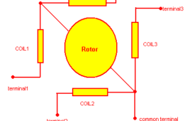
How to deal with any unknown stepper motor? This section deals with a special procedure that can be useful to find out the type of stepper motor, its terminals, its coil sequence, its step resolution and everything about stepper motor. if anyone have a steppe motor that doesn’t have any specifications then after going through this section…
ATtiny85 microcontroller tutorials, Part 4: LED chaser using ATtiny85
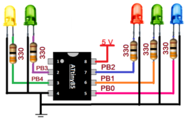
In the previous tutorial of this series, we have seen how to work with ATtiny85, how to program it, and also we have built our first – hello world application – that is LED blinking application using ATtiny85. So let us extend it to the next step – means one step advance. We shall connect…
DC Motor Control Using H Bridge

This article explains how one can change the direction and speed of mini DC motor using very simple circuit built using readily and easily available handy components. First we will see how we can change the direction of motor and then we will see how we can vary the speed of DC motor. Then I will explain very simple DC motor controller circuit that changes direction as well as varies the speed of DC motor. So let us start
Joystick Based Dual DC Motor Controller Using OP-AMP

All you might have seen controlling a DC motor using joystick.Most of RC toys are DC motor operated and they are controlled using remote controlled joystick. There is a RF transmitter in the remote controlled joystick and in a toy, there is RF receiver that rotates DC motor forward (clockwise) and reverse (anticlockwise)The remote controlled robotic vehicles used in military applications also controlled using such joystick connected with laptop or computerUnmanned air vehicles like drone, quad copter etc used for air surveillance or aerial photography/videography are the best examples of joystick control
ATtiny85 microcontroller tutorials, Part 1: Introduction
ATtiny85 microcontroller is a very popular 8-bit RISC microcontroller. It has become the first choice for professionals and developers because of its incredible features in such a small size. As its name suggests, it’s a tiny 8-pin (PDIP) microcontroller with almost all required features that any microcontroller should have such as built-in FLASH, EEPROM, SRAM,…