Microcontrollers are purely digital devices which work on logic0 and logic1 voltages; still they are widely used for analog signal processing. There are specialized signal processors chips available which are custom made for particular applications; however a general purpose microcontroller is more than enough for small kind of signal processing applications like audio signal input and output. The microcontroller can read the analog input voltage by sampling it and converting it to their digital values. The Analog to Digital Converter (ADC) available in almost all the microcontrollers help in this task. A timer can be used to generate the sampling time period. The sampled values can then read and modify by the microcontroller. The modified signal is then output by the microcontroller in the form of Pulse Width Modulated (PWM) waves. Most of the microcontrollers have the PWM module which helps them in generating analog voltage output at an external device.
How to Glow an LED using PWM with PIC Microcontroller- (Part 20/25)
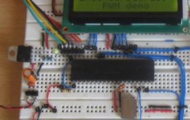
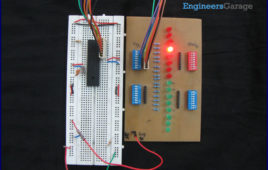
Pulse Width Modulation (PWM) is a technique in which the width of a pulse is modulated keeping the time period of the wave constant. One cycle has a fixed time period called ‘Period’ and a varying on time called ‘Duty cycle’. The entire wave can have two voltages levels either logic 0 or logic 1. The PWM wave is very useful in the digital systems, since this can be used to generate different voltage values other than the logic 0 or logic 1 values. This feature is making use in so many digital systems like DC motor control, audio devices, simple decoration light controls etc.The PIC18F4550 has an inbuilt PWM module which can generate continuous PWM waves. The Period and the duty cycle of the PWMwave can be adjusted in program. This project explores the PWM module of the PIC18F4550 and tries to glow an LED with varying intensities, which shows that it is possible to generate any required voltage at a pin of a digital microcontroller with the help of PWM waves.
How to Generate Sound using PWM with PIC Microcontroller- (Part 22/25)
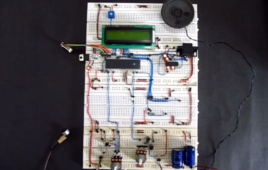
Pulse Width Modulation (PWM) is a technique in which the width of a pulse is modulated keeping the time period of the wave constant. The ON time and OFF time can have any different values in the wave cycles, but the sum of the ON time and OFF time remains same for the entire cycles. PWM is a digital wave that can be generated using digital circuits which are not capable of generating analog voltages. With the help of the modulation of the width of a pulse in a period of the wave, they can generate any required voltage with the help of a proper filter circuits. The filter circuits are used for generating the voltage corresponding to a modulated wave. This feature of the PWM wave is making use in so many digital systems like DC motor control, audio devices, simple decoration light controls etc. The PIC18F4550 has an inbuilt PWM module which can generate continuous PWM waves. This project explores the PWM module of the PIC18F4550 and tries generating a sine wave with frequency in the audible range and then produce that sound in a Loud Speaker with the help of a filter circuit and Loud Speaker driver circuits.
How to Generate Sine Wave using PWM with PIC Microcontroller- (Part 19/25)
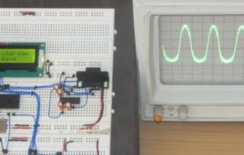
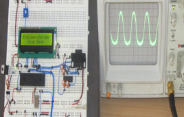
Pulse Width Modulation (PWM) is a technique in which the width of a pulse is modulated keeping the time period of the wave constant. The ON time and OFF time can have any different values in the wave cycles, but the sum of the ON time and OFF time remains same for the entire cycles. PWM is a digital wave that can be generated using digital circuits which are not capable of generating analog voltages. With the help of the modulation of the width of a pulse in a period of the wave, they can generate any required voltage with the help of a proper filter circuits. The filter circuits are used for generating the voltage corresponding to a modulated wave. Hence the PWM wave is always associated with a filter circuit.This feature of the PWM wave is making use in so many digital systems like DC motor control, audio devices, simple decoration light controls etc. The PIC18F4550 has an inbuilt PWM module which can generate continuous PWM waves. This project explores the PWM module of the PIC18F4550 and tries generating a sine wave with the help of a filter circuit. Generating a sine wave has a great deal of importance since the sine wave is the most natural waveform and all other kind of waves can be generated as a combination of sine waves with different frequencies and amplitude.
How to Implement SPI Using PIC18F4550- (Part 24/25)

The Serial Peripheral Interface (SPI) is a high speed, synchronous, serial communication standard. This communication protocol is basically a Master – Slave implementation where the master device controls the clock based on which the slave devices operate. The master communicates with a slave or a number of slaves in a system through the SPI bus. The SPI bus requires a minimum of three wires including SDO (Serial Data Out), SDI (Serial Data Input) and SCK (Serial Clock). Since it is a master controller system the SDO is also called MOSI (Master Output Slave Input) and the SDI is also called MISO (Master Input Slave Output). The SPI is a full-duplex high speed communication protocol. The master and slave can transmit and receive data at the same time. The master is the device which generates clock for all these data transmissions. Read PIC microcontroller tutorial based on PIC18F4550 microcontrollers in which one of the microcontroller acts as a slave transmitter and the other acts as master receiver. With the help of an LCD, this particular project demonstrates the complete data transfer between a master and slave when both the master and slave are transmitting and receiving the data at the same time.
How to use PIC18F4550 as a SPI Slave Transmitter- (Part 25/25)
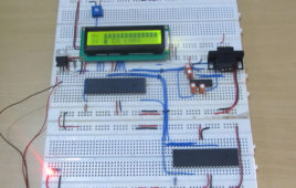
The Serial Peripheral Interface (SPI) is a high speed, synchronous, serial communication standard. This communication protocol is basically a Master Slaveimplementation where the master device controls the clock based on which the slave devices operates. The master can communicates with one or more slave in the system through SPI bus. The SPI bus requires a minimum of three wires i.e. a SDO (Serial Data Out), SDI (Serial Data Input) and SCK (Serial Clock). Since it is a master controller system the SDO is also called MOSI (Master Output Slave Input) and the SDI is also called MISO (Master Input Slave Output).The SPI is a full-duplex high speed communication protocol. The master and slave can transmit and receive data at the same time. The master generates clock for all these data transmissions.The SPI is special because it is simple and easy to implement in the hardware. The article explores the SPI hardware module of the PIC18F4550 microcontroller. This project will help in better understanding of the SPI protocol in detail.
How to use inbuilt EEPROM of PIC18F4550 Microcontroller- (Part 18/25)

The EEPROM (ELECTRICALLY ERASABLE PROGRAMMABLE READ ONLY MEMORY) is a very useful memory which can be used for storing data. The data storing and retrieving from any EEPROM memory is very simple compared to other kind of memories. As the name suggest the memory is electrically programmable and hence the data will be sustained in the memory until it is electrically erased or reprogrammed.There are lots of EEPROM chips available most of them are easy to interface with a microcontroller. It would be even better if the microcontroller itself has a built-in EEPROM. The microcontroller used in this project is PIC18F4550 and it also has an inbuilt EEPROM memory other than the flash memory. The data can be easily stored into or retrieve using simple codes. The PIC18F4550 has 256 bytes of internal EEPROM memory.The internal EEPROM of microcontrollers are very useful to store important data regarding their operation. They are used to store data like previous status, last log in/out time, last data received before shutting down or power failure.
How to interface GSM Module with PIC18F4550 Microcontroller- (Part 17/25)
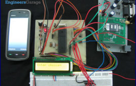
The Global System for Mobile (GSM) communication is the Second Generation of mobile technology. Although the world is moving towards Third and [[wysiwyg_imageupload::]]Fourth generation but GSM has been the most successful and widespread technology in the communication sector. GSM technology paved a new way for mobile communication.This project explains the interfacing of a GSM Module with a PIC microcontroller. It also covers a way to dial a particular GSM mobile number as well as send a message to it using AT Commands with the help of PIC18F4550.As explained earlier (refer GSM interfacing with 8051), a line converter MAX232 is employed to convert the RS232 logic data of GSM Module to TTL logic so that it can be processed by the microcontroller. In this project, instead of RS232 logic data, TTL logic output has been taken and thus PIC18F4550 has been directly connected with GSM Modem without any line converter in between. The following diagram shows the TTL input and output of GSM modem used.
How to interface Stepper Motor with PIC18F4550 Microcontroller- (Part 13/25)
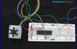
A Stepper Motor is a brushless, synchronous DC motor which divides a full rotation into a number of steps. For detailed information on working, types and stepping modes, refer the article on Stepper Motors. Here the operation of a unipolar Stepper motor with PIC18F4550 microcontroller has been explained.As stated earlier, a Stepper motor rotates step by step. Each stepper motor has a defined step angle which is the minimum degree of rotation in a single step. This step angle depends on the internal construction of the motor. If a stepper motor has a step angle of 1.8°, then it would need 200 steps for a complete circular rotation. For control operation, construction and stepping modes, refer the article on Stepper Motors.The stepper motor consists of a Rotor and four Stators. The stators are rounded with center-taped winding. The center-taped terminals are known Common terminals. Thus a unipolar stepper motor consists of total 6 wire-ends (four wires for coils and two for the common ends).
How to interface Servo Motor with PIC Microcontroller- (Part 21/25)

Servo systems use the error sensing negative feedback method to provide precise angular motion. Servo Motors are used where precise control on [[wysiwyg_imageupload::]]angular motion is needed. Servo motors are widely used in the field of Robotics to design robotic arms, palms, legs and so on. They are also used in RC toys like RC helicopter, airplanes and cars.The interfacing of servo motor using PIC microcontroller has been explained here. Readers are advised to go through the article on Servo Motors to learn basic mechanism and control of servo motor.A Servo motor has three wire terminals : two of these wires are to provide ground and positive supply to the Servo DC motor, while the third wire is for the control signal. These wires of a servo motor are color coded. The servo motor can be driven only when PWM (pulse width modulated) signals are provided to the control terminal. The total pulse duration for a typical servo motor should be of 20 milliseconds. The on-time duration of the control signal varies from 1ms to 2ms. This on-time variation provides angular variation from 0 to 180 degree. Also refer Servo motor control using 8051.
How to interface GPS with PIC18F4550 Microcontroller- (Part 16/25)

Global Positioning System is based on satellite navigation technology. A GPS Receiver provides the accurate location of an object in terms of latitude and [[wysiwyg_imageupload::]]longitude. Accurate time calculation with respect to GMT can also be done by using GPS. For more information on different data obtained through GPS, refer GPS Receivers. Here a PIC microcontroller has been interfaced with a GPS module to extract its position information (location). The main objective here is to find the location of the GPS Receiver in terms of latitude and longitude. The GPS module gives output data in RS232 logic level format. To convert the RS232 logic level into TTL, a line converter MAX232 has been connected between GPS module and PIC18F4550. (Also refer PIC USART) The circuit connection of GPS module with microcontroller is shown in the circuit diagram tab. The latitude and longitude data has been displayed on a 16×2 LCD interfaced to PIC.
How to interface RFID with PIC18F4550 Microcontroller- (Part 15/25)

RFID (Radio Frequency Identification and Detection) is widely used everywhere from highly secured defense laboratories to school attendance system. By [[wysiwyg_imageupload::]]employing RFID, much secured entry systems can be developed without incurring huge costs. These are the reasons of excessive use of RFID technology. In this article, interfacing of an RFID reader module has been explained with PIC18F4550. The USART interrupt, an internal PIC interrupt, has also been explained. (For more details on USART, refer PIC EUSART)As explained earlier (refer RFID interfacing with 8051 & with AVR), an RFID module consists of an RFID Reader, a line converter (usually MAX232) and a COM port. The line converter of this module converts the TTL logic voltage of RFID Reader to RS232 logic. Therefore, to convert the voltage level from such an RFID module, another MAX232 is used to interface it with a microcontroller. One can also use an RFID Reader directly to interface with the controller, thus avoiding the need of voltage level converters. Here both the MAX232s have been eliminated from the circuit and RFID reader is directly connected with the PIC microcontroller.
How to work with inbuilt Analog Comparators of PIC18F4550- (Part 12/25)

Analog comparator is an electronic device which compares the two voltage signals and provides TTL logic output to indicate the larger signal. The analog [[wysiwyg_imageupload::]]comparator is used in various applications where two inputs signals need to be compared. IR sensor is a very common example where analog comparator is used.PIC18F4550 has two in-built comparators which can be used in eight different modes. These in-built comparators save the cost and connections for providing an extra IC (like LM324, LM339 etc) in the circuit. This article explains the configuration of the analog comparators of this PIC microcontroller.PIC18F4550 consists of two analog comparators and these comparators can be used in eight different modes. The analog comparators’ I/O pins are multiplexed with PortA pins (RA0 – RA5) pins of the controller. The register CMCON is configured to set the mode of the comparator in a PIC microcontroller. Read more to find how PIC’s analog comparator is used to make this circuit.
How to configure EUSART in PIC18F4550 Microcontroller- (Part 14/25)

Both, Parallel and Serial modes of communication have certain advantages and disadvantages over one another. The serial communication is a preferred option due [[wysiwyg_imageupload::]]to its ability of long distance communication with error detection capability. The microcontrollers consist of an inbuilt hardware unit known as USART (Universal Synchronous Asynchronous Reception and Transmission) to facilitate serial transfer of data. Before starting USART, some general terms related to communication need to be understood. These terms are explained below.Asynchronous Communication: In this type of communication, both Transmitter (Tx) and Receiver (Rx) work on different clocks which means that they are not synchronized. Start and Stop bits are also sent with each Data byte to identify the data. Synchronous Communication: In this type of communication, both Tx and Rx are synchronized with the same clock and no Start or Stop bits are used.Full-duplex Communication: When either of the devices can send and receive data at the same instant, they are said to have full-duplex communication.
How to work with External (Hardware) Interrupts of PIC Microcontroller (PIC18F4550)- (Part 10/25)

Interrupts are special events that require immediate attention. They cause the processor to cease the running task to serve a special task for which the interrupt [[wysiwyg_imageupload::]]event had occurred. After the special task is over, the processor resumes performing the original task.The processor can also serve these events by polling method. But polling is an inefficient technique as compared to interrupts. In the polling method, the processor has to continuously wait for the event signal. Thus it always remains busy using extra resources. To understand the difference between polling and interrupts well, refer introductory paragraphs of 8051 Interrupts.Following is an example to illustrate the interrupts better. Suppose a programmer wants to make a real time watch which shows ambient temperature as well. The programmer has to use two internal peripherals of the controller, namely, a Timer and an ADC channel. Consider this project without using interrupt : the programmer has to take care of both peripherals one by one continuously by polling them. This is not an efficient way of programming.
How to work with inbuilt ADC Module of PIC Microcontroller (PIC18F4550)- (Part 11/25)
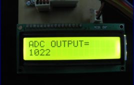
A microcontroller, a digital device, can read, execute and transmit only digital signals. On the contrary, the outputs of the most of the transducers are analog in [[wysiwyg_imageupload::]]nature. Thus it is hard to interface these transducers directly with controllers. Analog-to-digital convertor (ADC) ICs are one way to make the analog input compatible with the microcontroller.Using an external ADC adds complexity to the circuit. To avoid this complexity, PIC Microcontrollers have in-built ADC module which reduces the cost and connections of the circuit. This article explains the in-built ADC of PIC18F4550 controller.As mentioned in the summary, a PIC microcontroller has inbuilt ADC for A/D conversion. The ADC module of PIC18F4550 controller has following specifications:· 10-bit resolution output which means that an analog input gets converted into a corresponding 10-bit digital output.· 13 channels which means that a total of 13 analog signals can be converted simultaneously into digital.· Vref+ (RA3) and Vref- (RA2) pins for external reference voltage.· 8 selectable clock options.· ADC can be in auto-triggering mode for continuous A/D conversion.
How to use Timers in PIC18F4550 Microcontroller- (Part 9/25)
Timers as the name suggests pertain to time-related operations. They are mostly used for exact delay generation. Timers are also used in various other operations [[wysiwyg_imageupload::]]like PWM signal generation, auto-triggering of several other peripherals etc. The working and configuration of PIC18F4550 Timers have been explained in this article.Timers are the most essential peripheral for a microcontroller and every controller provides a provision for using them. Beginners are advised to go through the tutorial on Timers before going any further.For basic Timer operations, refer the Tutorial on Timers. PIC18F4550 is equipped with four Timers namely, Timer0, Timer1, Timer2 and Timer3. Before going for the details of Timer configurations, it is important to learn how time delay is calculated by the timer since exact delay generation is the most common application of Timers. Example: Given that a time delay of 1 sec is to be generated and a 12MHz crystal oscillator is connected with PIC. Please note that this example considers external clock source for the controller, however, PIC18F4550 has provision for both external as well as internal clock source.
How to interface 16×2 LCD in 4-bit mode with PIC Microcontroller (PIC18F4550)- (Part 7/25)
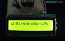
The 16×2 character LCD can work in two modes, namely, 8-bit and 4-bit. These modes basically correspond to the number of data pins used in interfacing LCD. 8-[[wysiwyg_imageupload::]]bit mode uses all the data lines and has been explained in LCD interfacing with PIC18F4550. In 4-bit mode, only four data pins of LCD are connected to the controller. This mode, thus, saves four pins of the controller unlike 8-bit mode. The configuration and display method of LCD in 4-bit mode has been explained here. The 8-bit mode of LCD interfacing with PIC has been explained earlier. In the 4-bit mode the (8-bit) data/command is sent in nibble (four bits) format to LCD. The higher nibble is sent first followed by the lower nibble. In 4-bit mode only four data pins (D4-D7) of LCD are connected to the controller. The control pins (RS, RW and EN) are connected the same way as in 8-bit mode.
How to create custom characters on 16×2 LCD using PIC18F4550- (Part 8/25)
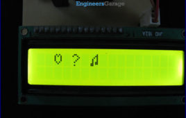
The 16×2 character LCD can also be used to display custom characters other than numerals, alphabets & special characters. Refer LCD interfacing with PIC. Some [[wysiwyg_imageupload::]]special shapes like hearts, arrows, smileys etc. can easily be displayed on the 5×8 pixel pattern of character LCD. These shapes are first stored at a special location in LCD’s controller and then displayed on the LCD module. This procedure has been explained here by using PIC18F4550. The special characters are generated by bit-mapping of LCD’s 5×8 bit pixel matrix. Refer Creating custom characters on LCD using 8051 for more details on bitmap generation and storing custom values in custom generator (CG) RAM of LCD’s controller. The mikroC IDE provides LCD Custom Character tool to create the bitmap of user defined custom character. Read further to know how are the characters created.
How to display text on 16×2 LCD using PIC18F4550 Microcontroller- (Part 6/25)
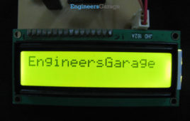
In Several automated and semi-automated devices require a message to be displayed in order to indicate their working status. In continuation to LCD interfacing [[wysiwyg_imageupload::]]with PIC18F4550, this article explains how to display a message or string on a 16×2 character LCD. In the previous article, a single character was displayed on LCD by properly configuring its data and command registers. A string is nothing but a sequential arrangement of several characters that can be displayed on LCD by using the programming steps mentioned here. The circuit connections and user-defined functions are same as earlier. The LCD data pins are connected to PortB of PIC18F4550 while the control pins are connected to first three pins. Read more to find how easily can one interface a display unit with a PIC micro controller.