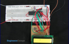
For basic details and operations of character LCD, refer LCD interfacing with 8051. Here LCD has been interfaced in 8-bit mode* with data pins (D0-D7) connected to PortB of PIC18F4550. The LCD control pins RS, R/W and EN are connected to PortA pins RA0, RA1 and RA2 respectively. *Character LCD can also be interfaced…
Seven Segment Multiplexing using PIC18F4550 Microcontroller- (Part 4/25)

As explained earlier, a seven segment interfaced with PIC uses almost an entire port (minimum 7 pins) to display a value. But a real time application, like watch, [[wysiwyg_imageupload::]]calculator etc., usually requires at least 3-4 seven segments. In such a case it is not advisable to use a port of the controller for each seven segment. In these cases, multiplexing technique is used to work with more than one seven segment. Here multiplexing of four seven-segments has been explained withPIC18F4550 to display four-digit count from 0000 to 9999. The multiplexing concept is based on the principle of persistence of human vision. A human eye cannot detect a visual change if the frames change at a rate of 25 (or more) frames per sec. This means that if events occur continuously with a time difference of less than or equal to 0.04 sec (1/25 sec), then we cannot notice the transition between those events.
How to interface Seven Segment Display with PIC18F4550 Microcontroller- (Part 3/25)

A typical seven-segment consists of 8 LEDs arranged in a pattern to display values. A seven-segment can be either of the two types, namely, Common Anode (CA) and Common Cathode (CC). For more details, refer Seven segments. A single seven-segment requires a minimum of 7 data pins of controller to display different values. The connections…