This is a simple shooting game comprising of an infrared pulse emitter and receiver. There are 8 white leds and one green led which will light up periodically. The player has to shoot at the receiver when the green led lights up. This is a simple beginner’s project and can be used to make more complicated projects like “LASER TAG GAME”. Infrared gun (transmitter) for this electronic game is built around IC1 timer (NE555) wired as an astable multivibrator with a centre frequency of about 35 kHz. The receiver circuit has 3 main ICs – 2 NE555s (one wired as an astable multivibrator and the other for monostable operation) and 1 CD4017B (decade counter). These circuits can be modified to make “LASER TAG GAME”. Read more to find out how IC555 is used in this circuit and how it works.
Understanding Potentiometers
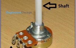
Potentiometers are the humblest electronic component we have in our modern day labs. Every time we turn a knob in our music system or play games with joysticks, we are actually turning a potentiometer (or pot) inside them. Plus they are cheap and readily available. These pots are extensively used in audio electronics and hence are also called audio pots. The reason for their wide use in audio electronics especially in volume control owes to the perception of loudness by human ears. If two sources produce sound, then the human ear will perceive one source twice as loud as the other only if the intensity of sound of one source is ten times the other. So by using audio pots we are able to achieve perceivable change in loudness by slight turning of the pot. If a linear pot is used instead, we will notice that loudness changes only when the pot is turned to its full extent
Impedance Matching & Buffers
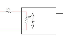
Sometimes we design and make circuits which function correctly in pieces but when the circuits are connected together, they do not give the expected result. For example, design a low frequency oscillator such as a Wien bridge oscillator and a common collector amplifier. Check their functioning separately and then connect the output of the oscillator to the input of the amplifier. If the design of the amplifier is not meticulous, most probably the output will not be as expected. This may be due to ignorance of a simple but a very important concept called impedance matching. So what is impedance matching? To understand this let us take a classic example where impedance matching is used, sound amplification using a microphone and a loudspeaker.
Obstacle/Edge Detecting and Avoiding Vehicle
The aim of the project is to build a robot which, in simple terms, is a hand and edge detecting and avoiding vehicle. When our hand comes from the top, it avoids it by moving away. Further, it will not fall off the table edge. Waking up early in the morning is very difficult to most of us. Hence to force you out of bed, Clockie is an expert. An alarm can be fixed on it. When you try to switch off the alarm to go back to sleep, the clockie avoids your hand and moves away. Also it makes sure that it wont fall off the table. So it forces you to get out of your bed and switch it off. Once you are out of your bed, you don’t (most of the time) feel like going back to bed(if you are really serious of waking up).
Impedance Matching & Buffers
Sometimes we design and make circuits which function correctly in pieces but when the circuits are connected together, they do not give the expected result. For example, design a low frequency oscillator such as a Wien bridge oscillator and a common collector amplifier. Check their functioning separately and then connect the output of the oscillator to the input of the amplifier. If the design of the amplifier is not meticulous, most probably the output will not be as expected. This may be due to ignorance of a simple but a very important concept called impedance matching. So what is impedance matching? To understand this let us take a classic example where impedance matching is used, sound amplification using a microphone and a loudspeaker.


