We have studied about the first program on the NRF module which was very simple and we have been successful in blinking the LED.Now, if we wish to make anything with NRF, we must know how to take analog inputs as most of the sensor is analog. In this article, we will see how to use the inbuilt ADC of NRF and how we can use any analog sensor and convert its value into digitalThe specifications we have extracted from the datasheet. Now to understand the code, we have taken an excerpt from the example codes provided by Nordic. Let’s understand the main part of code line by line.
Interrupts with NRF24LE1 (Part 3/14)

In our daily life we get distracted or interrupted by others many times. In that condition we suspend our ongoing work and pay attention to what others have to say. We only resume our previously suspended work after the completion of the interrupted task. The master which controls the processing of thoughts in us is our brain. The brain stops processing ongoing thoughts when we get interrupted and starts processing the other task. It resumes the previous ongoing processing when the task is complete. The controller works in a similar manner. Here, we will study interrupts associated with our NRF.
Power Failure Indicator in NRF24LE1 (Part 4/14)

Nowadays most of our devices are portable and run on batteries. We often do not know when the battery is about to get discharged. Many systems have the battery voltage display to indicate the battery voltage but what if we don’t have the display in our system. In such a case, using a small LED to indicate low battery is very helpful for users to know about the battery status.
Using EEPROM of NRF24LE1 (Part 5/14)

All the good and bad incidents are stored in the brain memory of humans. Similarly, the controller uses EEPROM to save data or variables. In this article, we will see how to use the EEPROM of NRF24LE1 and what are its uses?Do you know what makes the memory in electronics? Let’s take an example of a capacitor. It has the capability to hold voltage and thus it’s treated as memory component. There are two types of memories in electronics; Volatile and non-volatile. The volatile one gets erased if the power supplied to this memory is cut. That means the data stored will be erased in case of power failure. The non-volatile has an advantage of holding data even when the power is off. The most common example of volatile memory is the RAM used in our computers. The examples of volatile memory are hard disk, SD cards, EEPROM, etc
PWM with NRF24LE1 (Part 6/14)

Have you ever thought that the phone light, when turned ON, is not always ON? It fluctuates with a frequency to save some energy which our eyes can’t sense. It’s a cool thing to save some battery but how is this done? The answer is PWM. PWM is an important technique for producing analog voltages using digital voltages and controlling LEDs, DC, servo motor, etc. The time period of the generated wave will be the sum of delay for HIGH pulse and delay for LOW pulse. Reciprocal of time will give us frequency of the produced signal.
Timers with NRF24LE1 (Part 7/14)
Timers with NRF24LE1 Timing plays an important part in our life. It’s normal for a human to allocate time for future plans. We only need brain and a clock to decide what is the current time and how much time has passed. Similarly, a microcontroller can also calculate time. It serves the purpose of brain…
Random Number Generator with NRF24LE1 (Part 8/14)

Random number sometimes plays an important role in our life. Think of a lottery ticket you have purchased. Now what if a random number taken out of lottery lot matches your ticket number? We will be glad if that happens. Random number generators are also used in making games more puzzling and non-deterministic. Do you know microcontrollers too can generate random number? Today we are going to discuss an interesting feature of NRF24LE1 which is Random Number Generator (RNG).
Watchdog with NRF24LE1 (Part 9/14)

Till now in the series on NRF24LE1, we have covered many interesting and special features which differentiate NRF from others. Today we are going to discuss an important functionality of microcontrollers which helps them recover from failure. Suppose, I give you a task to solve in predefined time and you fail to do it in allotted time then you will have to start it from the beginning. The word ‘Timeout’ can be used here to clarify the concept.
UART communication using NRF24le1 (Part 10/14)

In this modern world we all are aware about USB. We all connect our Pen drives, memory card and other devices using USB. But have you ever thought what is it? Here is the answer; USB is a communication protocol by which two devices communicate with each other. In the same way, microcontroller also communicates with other devices like sensors or PC by using different communication protocols like USB, UART, and I2C.UART stands for Universal Asynchronous Receiver/Transmitter. It is a type of serial communication that uses two wires, one for transmission (Tx) and one for reception (Rx).
Ultrasonic sensor with NRF24LE1 (Part 11/14)

Today we are going to interface a very interesting sensor with NRF module.Have you ever heard bats communicating with each other? We can’t hear them because they use ultrasonic frequency to communicate with each other. Ultrasonic frequencies cannot be heard by human ears. Human can only hear sound between 20 – 20 KHz frequency whereas ultrasonic frequency lies above 20 KHz and expands up to several GHz.The ultrasonic waves have different travelling speed in air, liquid and gases. In air they usually travel at 340 m/s. They have the tendency to get reflected from a solid surface. Due to this functionality they are used in distance measurement.
Interfacing Accelerometer with NRF24LE1 (Part 12/14)

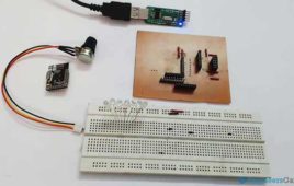
In this series we have learnt the basic functionalities and features of NRF24LE1. Now it’s time to use them for achieving higher tasks. In future, we will combine various functionalities of the NRF with outer world. Today, we will interface an accelerometer sensor with NRF24LE1 using ADC (Analog to digital converter). We will also output the acceleration reading to our PC using Serial communication.
Wireless Communication with NRF24LE1 (Part 13/14)

The invention of radio has revolutionized the world. It was a successful tool for communicating information using wireless communication. Another great invention was the telephone. Do you remember those days when we used those bulky landline phones? Now the era has changed. Landline phones are getting replaced by mobile phones. We have to accept the fact that wireless communication has become an essential part of our life. If we look around ourselves, we will find many devices which work on wireless communication like mouse, keyboard, lock keys, radio, cordless phone and much more. Also, wireless communication is sometimes referred as Radio Frequency (RF) communication.
Atmega 32u4 Based Multimedia Volume Controller (Part 11/25)

How a multimedia keyboard is made has been already explained in the Atmega 32u4 Based Multimedia Keypad Project. In that project a keypad was designed to control media functions of the window media player on windows OS. A set of tactile switches was used to receive the user inputs in that project. This project – Multimedia Volume Control will control main volume of the windows operating system.Also, in the project, instead of using tactile switches, LDR sensors are used for user inputs to demonstrate a gesture recognition application. Like in the multimedia keypad project, in this project as well, the device will be configured to a consumer device instead on generic desktop control device. In the USB protocol, when the usage page report item of the usage page of an HID device is configured to consumer type, the device gets configured for application specific controls.
Introduction to LUFA

Universal Serial Bus (USB) is now a common and vast framework for serial communication. The interface not only allows serial communication, it also works as electronic power supply. The popular AVR microcontrollers fortunately have the USB interface feature and can be programmed to build USB devices. The USB specification is long and intimidating. It can be a daunting task to write a device specific USB driver.
Introduction to USB: Advantages, Disadvantages and Architecture (Part 1/6)
Universal Serial Bus (USB) is the de facto interface for computer peripherals to communicate with the personal computers. The interface that saw the light of day around the mid-1990s was a joint effort of seven companies – Compaq, DEC, IBM, Intel, Microsoft, Nortel, and NEC.
USB Protocol: Types of USB Packets and USB Transfers (Part 2/6)
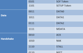
After discussing the features and architecture of USB, let’s move on to its protocol. A USB interface has several layers of protocol. Most of the time the lower level layers are single handled by host controller IC while the end designer needs to work on higher level layers. Every communication protocol involves the exchange of packets. Same is the case with USB. These packets encapsulate information in a standard-defined organized manner. These packets generally contain information related to- Controlling the data exchange, Data exchange in the form of actual payload, and Error detection and correction through the status check up. In USB the LSB of the packet is transmitted first. A USB packet contains different fields.
USB Requests and Stages of Control Transfer (Part 4/6)
In the previous article of this series, USB Descriptors were discussed. When a USB peripheral is connected to a host device, the host sends queries in the form of requests. The peripheral responds by sending Descriptors. The Descriptors contain the information required for identifying and configuring the peripheral device, implementing the interfaces and setting endpoints. The device descriptor is the first descriptor sent to the host and it helps in configuring the peripheral with respect to the host. The subsequent descriptors implement the functioning, the peripheral is meant for. The Control Transfer is the only transfer type which is supported even when the device is yet not configured. That is the reason, it is used for sending requests and obtaining the descriptors. The default endpoint is endpoint 0 which is bidirectional and used for control transfers.
Introduction to USB: Advantages, Disadvantages and Architecture (Part 1/6)

Universal Serial Bus (USB) is the de facto interface for computer peripherals to communicate with the personal computers. The interface that saw the light of day around the mid-1990s was a joint effort of seven companies – Compaq, DEC, IBM, Intel, Microsoft, Nortel, and NEC. These companies were aiming to replace the then parallel ports and the external power chargers with a universal communication standard that could simplify data exchange and could double duty to supply power as well.Nowadays, USB is the standard and must-have interface on almost all motherboards, single board computers and the embedded microcontroller boards and almost every digital peripheral from regular computer peripherals like keyboard, mouse and joysticks to smart digital devices.
USB Descriptors and their Types (Part 3/6)

Now that we have discussed the basic details of USB including its features, architecture, and protocol, the next topic in the series is USB Descriptors. In context to USB interface, Descriptors are formatted blocks of information, through which, the host device learns about the peripheral. It helps in identifying and configuring the peripheral device.A Descriptor contains information like type of the device, Vendor ID, Compliant USB Version, number of configurations device supports, number of endpoints, etc. The USB peripheral must respond with descriptors when requested by the host. During enumeration, the host uses control transfer to request the device for descriptors.
USB Requests and Stages of Control Transfer (Part 4/6)
In the previous article of this series, USB Descriptors were discussed. When a USB peripheral is connected to a host device, the host sends queries in the form of requests. The peripheral responds by sending Descriptors. The Descriptors contain the information required for identifying and configuring the peripheral device, implementing the interfaces and setting endpoints. The device descriptor is the first descriptor sent to the host and it helps in configuring the peripheral with respect to the host. The subsequent descriptors implement the functioning, the peripheral is meant for. The Control Transfer is the only transfer type which is supported even when the device is yet not configured. That is the reason, it is used for sending requests and obtaining the descriptors. The default endpoint is endpoint 0 which is bidirectional and used for control transfers.