
The designing of Boost Converter SMPS has been already discussed in the previous tutorials. In this tutorial, an open loop buck converter SMPS will be designed. The Buck Converter is also one of the topologies of the SMPS (Switched Mode Power Supply). These type of SMPS steps down the DC voltage unlike the Boost converters step up the DC voltage. So the buck Converter is also a DC to DC step down converter in which the output voltage is always less than the input voltage. Contrary to Linear Regulators which step down the DC voltage by dissipating the heat, Buck Converters step down the DC voltage through switching regulators and also step up the output current.
Designing Close Loop Non-Isolated Boost Converter With Adjustable Output (Part 4/12)

The closed loop boost converter designed in the previous tutorial though had a constant and regulated voltage at the output but it could not be varied. For a stable output that Boost converter had an error detection circuit. The error detection was done by adding a feedback circuit which continuously checks the error in the output voltage and provided a regulated voltage at the output. For making the output of the circuit adjustable, it must be drawn through a variable resistor. This closed loop boost converter not only had a feedback circuit, its output is also adjustable. Therefore in this tutorial, a closed loop non–isolated boost converter is designed.
Designing Open Loop Non-Isolated Boost Converter With Adjustable Output Voltage (Part 3/12)

The open loop boost converter designed in the previous tutorial had a fixed output voltage respective to the input voltage level. The output voltage of the circuit can be made variable by drawing the output through a variable resistor. The output voltage in this circuit still remains unregulated as no feedback is used.Therefore in this tutorial, an open loop non–isolated boost converter is designed. The boost converter can be designed in two ways- Open loop boost converter and closed loop boost converter. There are certain design parameters involved in the designing of the boost converter. It is important to understand these design parameters. Any boost canverter can operate in either of the two possible modes of operation.
Designing Closed Loop Non – Isolated Boost Converter SMPS (Part 2/12)

The open loop boost converter designed in the previous tutorial did not have constant and regulated voltage at the output. For a stable output, a Boost converter with error detection circuit needs to be designed. The error detection can be done by adding a feedback circuit which continuously checks the error in the output voltage and provides a regulated voltage at the output. Therefore in this tutorial, a closed loop non–isolated boost converter is designed. The boost converter can be designed in two ways- Open loop boost converter and Closed loop boost converter. In the former, there is no feedback from output to input contrary to the closed loop which has a feedback circuit. So, the output of an open loop boost converter is not regulated. In the latter, there is a feedback from the output to the input. So, the output of a closed loop boost converter is regulated.
Designing an Open loop Boost Converter SMPS (Part 1/12)

In this tutorial, an open loop boost converter SMPS will be designed. The Boost Converter is one of the topologies of Switched Mode Power Supply (SMPS). It has a DC source as Input power like a battery, generator or rectifier. In the case of a boost converter, the output power is always greater than the input power.So, the boost converter circuit will step up the power from one DC level to a higher DC level. The method of converting one DC voltage to a different DC voltage is called DC to DC conversion. The boost converter is a DC to DC converter which steps up the input signal to the higher voltage level.
Basics of Audio Amplifier – 1/9

Audio is one of the most common media. Here, It refers to the representation of sound which can be perceived by humans. Audio and Video are the essential component of any electronic media. The electronics can be used to receive audio signals (via microphone), record audio in some storage, transmit audio (through wired or wireless communication channels) and reproduce audio signals (via speakers). The audio can be represented and transmitted as either analog signals or digital signals. In this series, analog audio signals are the concern. The audio signals have a frequency range of 20 Hz to 20,000 Hz.
Designing Switched Mode Power Supply (SMPS)
Everyone must be familiar with the term – Switched Mode Power Supply or SMPS. Yes, they are used in every personal computer. In fact, the Switched Mode Power Supply is widely used with many other devices. Once it is understood that what SMPS actually is, its countless applications can be easily imagined. An SMPS is used for converting the electronic power supply efficiently. Any SMPS has some storage components which store electrical energy to supply to the load device and some switching components which turn on and off at high frequencies charging and discharging the storage components.
Audio Filters: Understanding sound waves – Part 1
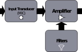
The audio electronics is a branch of electronics that deals with designing of circuits that convert sound into electrical signals or electrical signals back into the sound. These circuits all together form an audio system. Basically, an audio system is designed to receive audio signals (via microphone), record audio in some storage, transmit audio (through wired or wireless communication channels) and reproduce audio signals (via speakers). So, the audio circuits perform signal processing for representing the sound in the form of electrical signals, manipulate the electrical (audio) signals like amplifying, filtering or mixing, reproduce sound from the audio signals, store audio into computer files or reproduce audio from an audio file. All these processes are performed by different audio related circuits or devices.
Audio filters: Understanding acoustic waves – Part 2
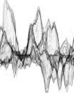
In the previous tutorial, sound wave and its properties were discussed. Now it’s time to understand Acoustic Waves. Generally, the term sound wave is used to refer the waves having frequency range audible to humans that is 20 Hz to 20 KHz. The waves having frequency greater than 20 KHz are called Ultrasonic waves and waves having a frequency range in Giga Hertz or higher are called Hypersonic Waves.
Designing Open Loop Isolated Push-Pull Converter (Part 12/12)

The Push-Pull is a DC to DC converter which uses a transformer for changing the DC power. The output voltage of the push-pull converter is either less than or greater than the input supply voltage. It is one of the topologies of the Switched Mode Power Supply so it works on the principle of switching regulators. In Push-Pull converter, the current is drawn in both halves of the switching cycle contrary to other converters like Buck-Boost or Flyback converter.Contrary to Linear Regulators, Push-Pull Converters use switching regulators. That is why the voltage is not altered by heat dissipation and the law of power conservation applies to these converter circuits. According to the law of power conservation, input power must be equal to output power.
Designing an open loop isolated flyback converter (Part 11/12)

A Flyback Converter is like a Buck-Boost DC to DC converter which provides the output voltage either less than or greater than the input supply voltage. It is one of the topologies of the Switched Mode Power Supply (SMPS) so it works on the principle of switching regulators.Flyback converter is similar to Buck-Boost converter with an exception that inductor used in Flyback converter has isolated winding. Due to isolated winding, the output voltage is non-inverting in the Flyback converter. So, a positive output voltage is obtained.
Designing Open Loop Non – Isolated Inverting Buck- Boost Converter with Adjustable Output Voltage (Part 10/12)

The Buck-Boost Converter is a DC to DC converter which provides the output voltage either less than or greater than the input supply voltage. It is one of the topologies of the Switched Mode Power Supply (SMPS), so, it works on the principle of switching regulators. A Buck – Boost converter can operate in either of the two modes – Buck Mode and Boost Mode. In the former mode, Output voltage is less than the input voltage, while in the latter, Output voltage is greater than the input voltage. Contrary to Linear Regulators, Buck-Boost Converters use switching regulators. That is why the voltage is not altered by heat dissipation and the law of power conservation applies to these converter circuits. According to the law of power conservation, input power must be equal to output power.
Designing Open Loop Non – Isolated Inverting Buck- Boost Converter (Part 9/12)
The Buck-Boost Converter is a DC to DC converter which provides the output voltage either less than or greater than the input supply voltage. It is one of the topologies of the Switched Mode Power Supply (SMPS), so, it works on the principle of switching regulators. A Buck – Boost converter can operate in either of the two modes – Buck and Boost. Contrary to Linear Regulators, Buck-Boost Converters use switching regulators. That is why the voltage is not altered by heat dissipation and the law of power conservation applies to these converter circuits. According to the law of power conservation, input power must be equal to output power.
Designing Closed Loop Non – Isolated Buck Converter With Adjustable Output (Part 8/12)

The closed loop buck converter designed in the previous tutorial though had a constant and regulated voltage at the output but it could not be varied. For a stable output that Buck converter had an error detection circuit. The error detection was done by adding a feedback circuit which continuously checks the error in the output voltage and provided a regulated voltage at the output.For making the output of the circuit adjustable, it must be drawn through a variable resistor. This closed loop buck converter not only had a feedback circuit, its output is also adjustable. Contrary to Linear Regulators which step down the DC voltage by dissipating the heat, Buck Converters step down the DC voltage through switching regulators and also step up the output current. According to the law of power conservation, input power must be equal to output power.
Designing Open Loop Non-Isolated Buck Converter With Adjustable Output Voltage (Part 7/12)

The open loop buck converter designed in the previous tutorial had a fixed output voltage respective to the input voltage level. The output voltage of the circuit can be made variable by drawing the output through a variable resistor. The output voltage in this circuit still remains unregulated as no feedback is used. Contrary to Linear Regulators which step down the DC voltage by dissipating the heat, Buck Converters step down the DC voltage through switching regulators and also step up the output current. According to the law of power conservation, input power must be equal to output power.
Make a 3.7 V Li – ion Battery Charger using TP-4056 (Part 9/9)

A battery charger is a circuit that recharges a battery by resupplying charge carriers (electrons) to it. The charging of the battery depends on the type of the battery. There are many types of batteries using different electrolyte materials. Irrespective of the type, the batteries have a common problem of overcharging and over discharging. Different batteries have different tolerance limit for overcharging. Some batteries are so sensitive that they may explode after a certain limit of charging. In order to avoid overcharging and consequent damage to the battery, an intelligent charging circuit needs to be designed. This circuitry will be responsible for charging the battery and when the overcharging voltage is reached, it should cut off the charging process. In this project, smart charger for Li-ion batteries is designed. The batteries considered for charging are taken of 3.7 V specification.
Automatic Power Supply Switching For Battery Operated Devices (Part 8/9)

In this experiment, a 12V lead acid battery is taken. The end of discharge voltage of 12V lead acid battery varies among the manufacturers. In this experiment, the battery used has an end of discharge voltage of 11V and its maximum rated terminal voltage is 13.8 V. During the project development, it was observed that when the battery reached to 11.04 V then the load circuit automatically connected to the DC source and so the battery was saved from deep discharge. When the battery was fully charged to 13.9 V then again the load connected to the battery. In this project, a feature to automatically charge the battery when the battery is discharged and again switch the battery to load when it is fully charged is desired. In this circuit when the battery will go below its end of discharge voltage i.e. approximately 10.7 V, then the relay will activate.
Make a Battery Level Indicator using LM339 IC (Part 7/9)

This era is an era of portable devices. Like smartphones and tablets are small computers that can be taken anywhere, more and more gadgets that can be taken anywhere are the new craze. These light-weight and portable devices are being developed in domains of electronic applications. All such devices are run on batteries.The batteries are the lifeline of all such devices. The use of batteries itself though requires certain precautions. The most common issue with the use of batteries is their overcharging and over discharging. Also, it is important to keep track of the charge level of batteries attached to a device, so that it can be timely charged before it discharges to the level that the device gets nonoperational.
Introduction to Uninterruptible Power Supply (UPS) and its design (Part – 1/17)
The Uninterruptible Power Supply (UPS) is an electronics device which supplies power to a load when main supplies or input power source fails. It not only acts as an emergency power source for the appliances, it serves to resolve common power problems too. Any UPS has a power storage element which stores energy in the form of chemical energy like the energy is stored in batteries.It is like energy is stored in the form of motion in a flywheel. That is why these devices are also called battery backup or flywheel backup. The UPS not only provides emergency power, they also help to sort out common power related issues like providing protection from input power interruptions, protection from overvoltage, output voltage regulation and stabilization.
Basics of Li-ion Battery Charging (Part- 3/17)
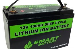
Lithium-ion batteries are another popular type of batteries that are used in the Uninterruptible Power Supply (UPS) designs. These batteries are commonly used in portable electronic devices. These are low maintenance batteries having high energy density, small size and light weight which makes them suitable for use in most of the portable devices. But, due to high energy density in comparison to the weight and volume of the Li-ion Battery, there are also some safety concerns while charging the Li-ion batteries. Before designing a charger circuit for these batteries, let us first understand charging methods and topologies involved in charging Li-ion batteries. Also, precautions required in handling, storing and disposing of these batteries are must to know.