
In this project a protoype circuit which can switch on the device when the light falls on it. For this I will use LM358 IC which is operational amplifier. I have made the circuit with LDR and few more components. But when I interchange the LDR with photodiode, phototransistor and transistor (L14F1) my circuit works well without changing any other components. Before understanding the circuit which I have developed, first let’s have a look on the components used in the circuit.LM358 consists of two independent, high gain operational amplifiers in one package. Important feature of this IC is that we do not require independent power supply for working of each comparator for wide range of power supply. LM358 can be used as transducer amplifier, DC gain block etc.
8 LED Flasher with Flashing Speed Control
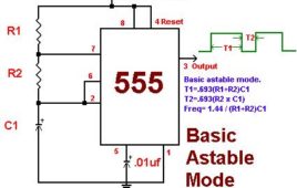
The 8-LED Flasher is built around Timer and Counter ICs. It Flashes 8 LEDs sequentially and the flashing speed can be controlled by a potentiometer. This can be used as a design pattern for decoration. But theoretically, it clears the Timer and Counter concepts in an easy way.The circuit comprises of various components like 555 Timer IC, Decade counter (CD4017), LEDs, Resistors, Capacitors, Wires & a 9V battery. The monolithic integrated circuit 555 timer can be used as square-wave generator, linear saw-tooth generator, pulse generator, time delay generator, etc. here we use it to generate square waveform i.e. it is used in the Astable Mode with a duty cycle of 66.6%.The 8 LEDs could be arranged in any pattern and thus be used as a decorative Light Toy in your living room.
Reverse Parking Sensor
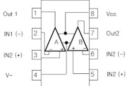
There are times when it is difficult to judge the distance while reversing the car or while parking. If someone is there to help you that is great but in situations when you are driving alone then what will you do? Or you are a new driver and cannot judge the distance? This circuit will solve all these problems. You can easily install at the back side of your car. Operated at 5V power supply and can also recharge batteries. You can also use them as shadow alarm at doors to protect your car. When shadow of a intruder fall on it will also give you alarm. This alarm will provide you the musical sound that’s why it will not tease your ears. Main components of this circuit areLM358 IC, LDR, UM66 IC, speaker and few more discrete components.LM358 consist of two independent, high gain operational amplifier in one package. Important feature of this IC is we do not require independent power supply for working of each comparator for wide range of power supply.
Designing Interesting Applications with IC555 Monostable Multivibrator
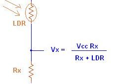
You might have seen so many applications and circuits based on monostable multivibrator using IC555 like intruder alarm, automatic night lamp, smoke detector, fire alarm, automatic gate controller, object counter etc. In all such circuits monostable multivibrator is used. We may easily understand the operation of the circuit but many of us don’t know how such circuits are designed. So here I will try to explain how such circuits are designed using some examples.To detect the light we need any photo sensor and the LDR is one of the most convenient photo sensor. It works on photo conductivity principal. That means its resistance varies as light falls on it. In absense of light the resistance of LDR is maximum and as light intensity increases the resistance decreases. So we can use this property in designing this circuit. As the resistance of LDR changes, the voltage across it also changes and this voltage is used to trigger monostable multivibrator.
Visitor Counter
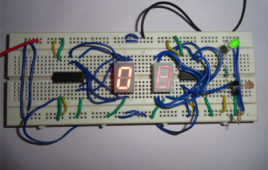
The circuit developed here will count the number of visitor entering or exiting from door of auditorium or hall or any other place. Depending on the interrupt from the sensors, the system identifies the entry and exit of the visitor. On the successful implementation of the procedure, it displays the number of visitor present in the room. Therefore it can be economically implemented in all the places where the visitors have to be counted and controlled. This circuit is good enough for only one person entering at a time. It will also give you visual indication of circuit with the help of LED. It is operated at wide range of temperature from 5V to 20V. The big advantage of the 4026B counter IC is that it can drive a 7-segment display without needing a decoder driver IC. It will count the number of visitor up to 99 which can be increased by cascading more 4026 IC.
Simple LDR Dark Sensor Circuit
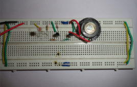
The circuit described here stops the musical sound when darkness is detected like when you put your hand above the sensor. This circuit can be used as morning alarm. Install it on your window so when the light falls on it will start giving you melodious sound to wake up. In night you can use it to switch off the light of staircase. When you switch off the light of your room with little modification like you can connect relay at output (in place of speaker) to off the bulb. This circuit can be operated with pencil cell as it require less only 3V for its operation. It can easily be mounted because of number of components used in circuit are quite small. LDR is a device whose sensitivity depends upon the intensity of light falling on it.
How to Make a TV Remote Control Jammer
This circuit confuses the infra-red receiver in a TV. It produces a constant signal that interferes with the signal from a remote control and prevents the TV detecting a channel-change or any other command. This allows you to watch your own program without anyone changing the channel!! The circuit is adjusted to produce a 38 kHz signal. The IR diode is called an Infra-red transmitting Diode or IR emitter diode to distinguish it from a receiving diode, called an IR receiver or IR receiving diode. (A Photo diode is a receiving diode). There are so many IR emitters that we cannot put a generic number on the circuit to represent the type of diode. Some types include: CY85G, LD271, CQY37N (45¢), INF3850, INF3880, INF3940 (30¢). The current through the IR LED is limited to 100mA by the inclusion of the two 1N4148 diodes, as these forms a constant-current arrangement when combined with the transistor and 5R6 resistor.
Logic High and Low Indicator on 7 Segment Display
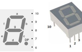
Logic high and low indicator is used to measure the voltages (high and low). For measuring the logic state high or low just put the probe on that point and you get the display on 7 segment display. This circuit will display “H” if voltage is high and it will display “L” when voltage is low. This simple circuit is based on 555 timer which act as a bi-stable multi-vibrator and two common anode seven segment display used as indicator to display logic state and few more discrete components. In bi-stable mode 555 timer act as a basic flip flop. We have club the pin 2 and 6 that is trigger and threshold pin and the voltage which is to be measure must be applied on this pin. When this pin 2 is low, circuit is in set position and changes the output state to high. And when pin 2 is high output pin 3 is low. It will hold the state either high or low indefinitely that is why it is called bi-stable multi-vibrator. We have connected the pin 4 with the switch which is used to reset the circuit. Pulling the reset input to ground acts as a ‘reset’ and transitions the output pin to ground (low state).
Automatic water level controller

Water level controllers are quite common nowadays. This circuit is based on popularly used IC555 IC. Water level controller circuits have these advantages: Most the circuit only display the amount of water present in circuit, but this circuit will “on” and “off” the motor according to the level of water present in tank. It will not automatically stop the motor when tank is fill but it will “on” the motor when water in tank reaches below a specific point. It can be easily installed in over headed tanks because of less components used in circuits. It prevents the wastage of water due to over flow of tank. Can be operated with the help of 12V battery or adaptors (converts 230V AC to 12V DC) readily available in markets.
Transistor Based Vehicle Indicator
While driving car, Before taking a turn it is a good practise to use the indicator, which will not only alert the other vehicle driver nearby you but reduces the chances of accident as well. But if your vehicle indicator is not working well then you can use this simple circuit. In night many accident took place because of less traffic, high speed and casual driving. We forget to use indicator and speeding vehicle behind you or from opposite side does not get time to slow or stop their vehicle. Therefore the use of indicator is always required in driving and while turning. This small circuit can also be used for two wheeler even in bicycle. Main advantage of this circuit is, it will not only give a visual indicator but also give you a buzzer sound while turning left or right.
Johnson Counter: How to use IC CD4033
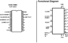
CD4033 is a Johnson counter IC commonly used in digital display. It has a 5 stage Johnson decade counter with decoder which convert the Johnson code to a 7 segment decoded output. Means it will convert the input into numeric display which can be seen on 7 segment display or with the help of LED’s.
FM Remote for Toycar
This is very much interesting application and I think you will surly build it. Any battery powered toy car can be made to run or stop from a remote place (around 100 mts) using this remote. Because it is RF remote you can operate your toy car through the obstacles (like wall, partitions etc.). So it will be a real wireless control for toy car.
8 channel IR remote with SM5021B & SM5032C Chips
This is single chip remote because transmitter and receiver are made up of single chip SM5021B and SM5032C respectively. Both chips are perfectly design for IR remote system by “Samhop microelectronics corp.”. It is an 8 channel remote with 2 inbuilt on/off controls & 6 pulse outputs. Before starting the project first go through the datasheets of both ICs.
Remote Unipolar Stepper Motor Controller with 89C51
This is the third and most amazing application of multichannel IR remote where 4 different channels of remote are utilized to control all the parameters of unipolar stepper motor. All three parameters of stepper motor RPM, direction & no. of revolutions can be changed from remote. 89C51 takes care of all the controlling actions.
DC Motor Controller with IR Remote

Here is the second application of multichannel IR remote. Using this application you can control the operation of DC-Motor from remote place. By means of controlling a DC-Motor you can # Start or stop DC-Motor # Change the direction of it either forward (Clockwise) or reverse (anticlockwise) # You can increase or decrease speed of it in any direction
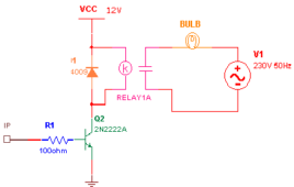
IR Remote Control for Home Appliances
This is first and most popular application of multichannel IR remote control where microcontroller 89C51 is used to switch ON/OFF four different home appliances (like tubelight, bulb, night lamp etc.). One can connect any device which has ON/OFF operation and which works on available domestic supply.
IR Remote for Toycar
This is a small but very interesting and funny project. We all may have played with the toy motorcar in our childhood. Now a days the toys which are available in the market are more attractive and more advance. One of the most interesting toy is remote-controlled motorcar or motorbike. The market price of such toys are around 600/- Rs. to 1000/- Rs. or more. So may be one cannot afford it. So here is the solution for it. If you have a battery powered (Pencil cell) toy-car at your home you can make it remote-controlled using this circuit with the budget of only around 100/- Rs.
IR Remote Switch
This is a single channel IR remote control switch. If you are a beginner or interested in small, easy and cheap remote control then this is the best one. This may be the easiest remote control to build. Using this remote control you can operate (ON/OFF) a single device from a remote place. Device may be AC or DC operated. Here I have used it to ON/OFF any AC device which operates on 230V like fan, bulb, tube-light, table -lamp. The range of this remote control is around 10 meters.
Generating time delay using astable mode of 555 timer IC
This circuit based project demonstrates the working of 555 timer in astable mode to generate pulses of time period 0.5 second. This pulse can be further used [[wysiwyg_imageupload::]]for anything where we need a pulse such as to blink a LED or to create fashionable blinking lights. This circuit of this project makes the use of timer IC NE555 which produces a constant square pulse of a desired frequency. This pulse could be either triggered or could be produced continuously depending upon the mode of 555 we are using. The two mostly used modes of 555 are Monostable and Astable. Here it is used in the astable mode with time period of half second, with high time period of 0.333 seconds and low time period of 0.166 seconds. Keep on reading to find out how the circuit is constructed and in what mode does the 555 IC works.
Piezo sensor as audio input using darlington pair

The generation of electric potential by the application of pressure, strain or any force is known as the piezoelectric effect. This effect can also be implemented to sense any audio signal. This can be achieved by using a piezoelectric diaphragm as audio sensor as shown in this project. Apart from the piezo sensor, other parts used in the circuit are as follows:1.Transistor BC5482. Resistances3. Speaker, and4. Capacitances