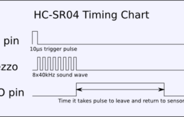
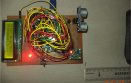
HC-SR04 based Distance Finder gives the distance from an obstacle in centimetres. It has a range of 2cms to 400cms. The project is build around AT89S52 which 8051 based microcontroller. The distance is displayed on Seven Segment Displays.The working of the ultrasonic sensors is quite simple and they are easy to interface with the microcontroller. The sensor module has 4-pins out of which Pin-1 and Pin-4 are +Vcc and Gnd respectively.Pin-2 is Trigger and Pin-3 is Echo pin.When a High pulse of 10us is applied at TRIG pin, the ultrasonic transmitter sends 8 consecutive pulses of 40kHz frequency. As the Eighth pulse is sent the ECHO pin of the sensor becomes HIGH. Now when the ultrasonic waves reflect from any surface and are received by the Receiver, the ECHO pin becomes LOW.
Android Phone Controlled Robot using Arduino
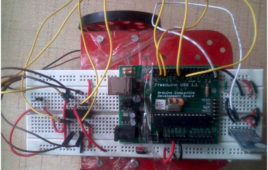
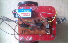
The Android phone that stays in your hand most of the time is useful in many other applications apart from Whatsapp, Facebook; appliances; monitor your health parameters. How it would be if it can control a Robot, which can assist in your daily work. With this project you can make a robot that can be controlled by an Android Phone, over Bluetooth Communication.The robot is built around Arduino interfaced with a Bluetooth receiver to receive commands from Android Phone.The basic Block diagram of the system is as:The operation being very simple, as the app on the phone transmits data serially over a Bluetooth connection established between it and the receiver.The commands are received and are processed according to the program fed into Arduino, upon which the further controlling is done. Motors are given instructions, in the way user commands them through his phone.
Generating Different Colours from RGB LED using Arduino PWM
RGB-LED is widely used to generate different colour Lights in Interior Decoration, Electronic Appliances, Automobiles, etc.This article deals with Arduino to get various colours with RGB LED and show the transition from one colour to another.
Interfacing Flex Sensor with Arduino
‘Flex Sensor’ or ‘Bend Sensor’ is a sensor that changes its resistance depending on the amount of bend on the sensor. They convert the change in bend into electrical resistance – the more the bend, the more the resistance value.Flex sensors are widely used in various applications such as – Automotive controls, Medical Devices, Fitness Products, Virtual Reality gaming consoles, Animatronics, Robotics, etc.This tutorial aims to provide a detailed guide to flex sensor and its interfacing with Arduino.
Home appliance control using Android phone
With increasing technology, Automation has become a need whether it is home, office or some other place. At home we come across many appliances be it Fan, AC, TV, Lights, etc. What if you could operate all of them with the Android Phone you’re holding in your Hand..!!This Project aims to incorporate android phone control over electrical appliances. We use Bluetooth communication between Android phone and a Receiver (control unit) that is connected to the appliances.
8 LED Flasher with Flashing Speed Control
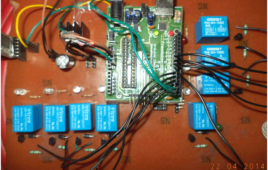
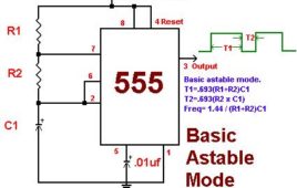
The 8-LED Flasher is built around Timer and Counter ICs. It Flashes 8 LEDs sequentially and the flashing speed can be controlled by a potentiometer. This can be used as a design pattern for decoration. But theoretically, it clears the Timer and Counter concepts in an easy way.The circuit comprises of various components like 555 Timer IC, Decade counter (CD4017), LEDs, Resistors, Capacitors, Wires & a 9V battery. The monolithic integrated circuit 555 timer can be used as square-wave generator, linear saw-tooth generator, pulse generator, time delay generator, etc. here we use it to generate square waveform i.e. it is used in the Astable Mode with a duty cycle of 66.6%.The 8 LEDs could be arranged in any pattern and thus be used as a decorative Light Toy in your living room.
Universal IR Remote Control
With technological advancements in consumer electronics, nowadays almost every appliance in our home is remote controlled.Managing a different Remote for TV, AC, Fan, DVD, DTH, etc., is quite difficult. What if we could have only one remote capable of working as a dedicated remote for any appliance any time.Presented here is such a device based on Arduino that can act as Remote control for any appliance when needed.
TV Remote Controlled Robot using Arduino
Basically, the Remote controls of Electronic Appliances be it TV, DVD, etc., work on IR communication principles. They transmit a code, in the form of IR pulses which is decoded by the reciever to carry out a specific operation. Each key has been assigned a specific code based on a certain standard protocol developed by the manufacturer.There are number of protocols that have been developed till the date by various manufacturers including Sony, Philips, etc. Some of common and widely used protocols are Sony SIRC, Philips RC5/RC6, NEC, etc.
Angle and Distance Measurement Device using Arduino
This project demonstrates the interfacing of Accelerometer (ADXL335) with Arduino and calibrating it to measure Angle from a reference plane. Also measuring the distance from object in its line of sight. The sensor data is fed to Arduino (Analog Input), it is processed and then the values are displayed on and 16×2 LCD.ADXL335 is 3-axis accelerometer with analog output from Analog Devices. ADXL335 acceleration measurement range is +/- 3 g. The Voltage requirement of IC-ADXL335 is typically 3.3V, but the module has on board regulator, which facilitates connection of 5V supply to it. It is extremely Low-Power device.
Interfacing LCD and Matrix Keypad with ARM LPC2138
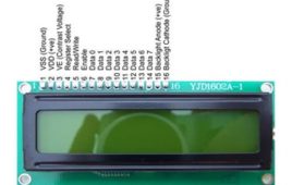
16×2 alphanumeric LCD can display 16 characters in each of its row, and it has two rows. To interface an LCD we need to know about its internal registers and pin functions. An LCD has two important registers namely command register and Data register. Both are 8-bit registers. The command register is written with various commands by the user. These commands are responsible for the functioning of LCD. 16×2 LCD is widely used in various embedded applications. The reason for this is its easy operation and it can display a large number of characters and symbols. In this tutorial we’ll interface LCD with ARM7 based microcontroller LPC2138.LCD can be interfaced in 8-bit as well as 4-bit mode (mode signifies Data bits sent at a time). In the 8-bit mode we require 8-pins of the microcontroller whereas in 4-bit mode the data is sent ‘nibble’ by ‘nibble’ (4 data lines used).
How to Interface 7 Segment Display with ARM7 based LPC2138 Microcontroller
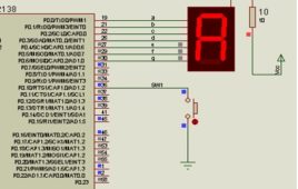
Seven segment displays are very commonly used in meter displays, etc. In this tutorial we’ll interface seven segment display(s) to our ARM7 based microcontroller LPC2138. For those who are new to ARM refer to previous tutorial (LED Interfacing). The task is to display all Numbers (0-9) and Alphabets on SSD. LPC2138 is a 32-bit microcontroller, so while coding we’ll be dealing with IO Registers that are 32-bit wide. For Interfacing a 7-segment we choose P0 (P0.0 to P0.7; 8 Pins out of 32 IO Pins on Port-0).Let’s use a common anode type display, a simple push-button switch, Resistors, etc. a,b,c,d,e,f terminals of display are connected to P0.0 to P0.6 respectively. Common terminal is supplied with +Vcc through a current limiting resistor R. Keep on reading to find out how whole system is assembled and what coding is applied to make it work.
2x2x2 LED Cube
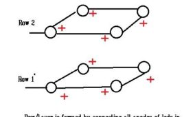
Smallest LED cube bringing up the Big concepts in Microcontroller Timing cycles. It consists of 8 LEDs being controlled through microcontroller to give amazing lighting Effects. A must try DIY project for beginners which can be extended to 4x4x4 or 8x8x8 and further, with 2x2x2 cube as the basic building block. The construction of LED cube is quite simple and easy to grasp. We have to construct two layers/rows of 4-LEDs in each. These two rows will then be connected together. To understand the working, let us consider that we want to ON an LED at position. For this we send a HIGH at one Terminal of cube through a transistor (A transistor is used because current through microcontroller is not sufficient to drive more than 1-2 LEDs) and a LOW at C0 terminal. This makes a complete path for the current and LED glows.
Introduction to ARM Microcontroller – LED Interfacing with LPC2138 (ARM7)
With the exponentially increasing modernization in Electronics Field, particularly in Embedded systems, it’s now a necessary step for Engineers, students and hobbyists to move along with Industry. There’s a need to grasp skills on recent industrial tools and systems. ARM Processors are one of such advancements in Embedded stream which serve as major platform for many of the modern systems. ARM stands for 32 bit Advanced RISC (Reduced Instruction Set Computer) Machines designed and licensed by British company ARM Holdings. As an IP core business, ARM Holdings itself does not manufacture its own electronic chips, but licenses its designs to other semiconductor manufacturers. ARM-based processors and systems on a chip include the Qualcomm Snapdragon, TI, etc. Using a RISC based approach to computer design, ARM processors require significantly fewer transistors than processors that would typically be found in a traditional computer.
Interfacing Servo Motor with Arduino MEGA-2560
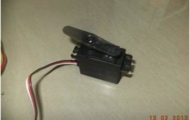
Servo motor is widely used by many engineering students and hobbyists in various applications. One major application is Robotics. Servo motor is used because it is easy to operate (PWM technique). It can maintain 90%of its rated torque at high speed. Sometimes a servo can provide up to twice its rated torque for short duration. Also, a servo operation is vibration-less and is free of resonance issues. This article is about interfacing a servo motor with Arduino Mega series board.
Arduino Tutorial: Blink an LED using Bluetooth
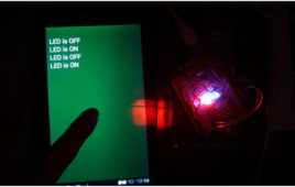
Bluetooth is a wireless technology standard for exchanging data over short distances (using short-wavelength UHF radio waves in the ISM band from 2.4 to 2.485 GHz) from fixed and mobile devices, and building personal area networks (PANs). Invented by telecom vendor Ericsson in 1994, it was originally conceived as a wireless alternative to RS-232 data cables. It can connect several devices, overcoming problems of synchronizationThis project aims to control an LED via Android Phone using Bluetooth Communication through commonly used module HC-05. For controlling we use an Arduino board with an Atmega8 sitting on it.
Arduino Modelling in MATLAB-Simulink
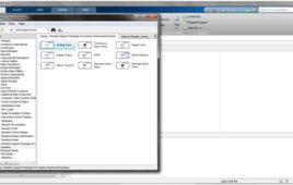
SIMULINK is a block diagram based tool, in which there’s no requirement to write a code in C or so, rather the block diagram model is directly converted and uploaded to the board by MATLAB tools. To begin with we will generate an LED Blink code and run it on Arduino-UNO.But Before getting to it, you need to check for some pre-requisites. Your Computer must have Matlab-R2013 or above, (This tutorial is on MATLAB-R2014a). If you have Student version of MATLAB -2013 or 2014, it will do.

