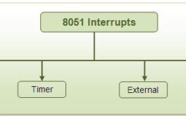
What is a Timer A timer is a clock that controls the sequence of an event while counting in fixed intervals of time. It is used for producing precise time delay. Secondly, it can be used to repeat or initiate an action after/at a known period of time. This feature is very commonly used in…
Interrupts & Programming 8051 Hardware Interrupts
Interrupt is one of the most important and powerful concepts and features in microcontroller/processor applications. Almost all the real world and real time systems built around microcontrollers and microprocessors make use of interrupts. What is Interrupt The interrupts refer to a notification, communicated to the controller, by a hardware device or software, on…
Simple Programs in 8051 Assembly Language
Here some simple assembly language programs for 8051 microcontroller are given to understand the operation of different instructions and to understand the logic behind particular program. First the statement of the program that describes what should be done is given. Then the solution is given which describes the logic how it will be done and…
8051 Instruction Set
Here one can find complete instruction set of 8051 microcontroller. Complete information regarding each instruction like operational explanation, addressing mode, no. of byte occupied, no. of cycles used etc is given. So just, go through it. It’s a ready reference. The complete 8051 Instruction Set or all 8051 instructions are broadly classify in to…
Interfacing ADC0808 with Serial port (RS232) using interrupt clock from 8051 microcontroller (AT89C51)- (Part 27/45)
In many applications data collected from multiple sensors is transmitted to PC for display or further analysis. The conversion of data from analog to digital form is done using an ADC. The digital data from the ADC is transferred to the computer using serial port. This circuit demonstrates the principle and operation of interfacing an ADC0808 with serial port of PC using the microcontroller AT89C51. The circuit is divided into three parts: ADC, controller and serial port. This circuit can be used as an intermediate circuit in many applications.ADC0808 which is an 8-bit resolution ADC has eight input channels i.e., it can take a maximum of eight analog inputs. The circuit uses the first analog input pin to take the analog input signals from the preset. To provide clock input to the ADC, Timer0 is used in interrupt enabled mode to generate a clock of frequency 500 KHz. To enable the Timer0 in interrupt enable mode, the register IE is loaded with the value 0x82. Every time the timer completes the counting, pin P1.2 toggles its state.
How to interface Serial ADC0831 with 8051 Microcontroller (AT89C51)- (Part 30/45)
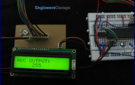
ADC is an electronic device which converts analog signals into its corresponding digital signal. This article demonstrates the principle, operation and interfacing of 8-bit serial ADC0831 with 8051 microcontroller.ADC0831 is an 8 pin IC with 8-bit serial data output (for more detail about ADC0831 refer to Interfacing ADC0831 with ATmega16). To receive the output from ADC high to low pulse is given at CS (chip select) pin of ADC form controller. ADC requires delay of two clock pulses before starting data conversion. At the second clock cycle, ADC sends a ‘0’ bit to the controller which indicates that the upcoming bits are the data bits.ADC needs eight clock pulses to send 8-bit digital output. This digital data is received bit by bit and stored in a variable. The data is converted to its corresponding ASCII value and sent to LCD for display. The connections of LCD with microcontroller are shown in circuit diagram. The analog signals are generated by at a variable resistance (preset) which is connected to input pin of ADC0831.
How to create custom characters on 16×2 LCD using 8051 microcontroller (AT89C51)- (Part 10/45)
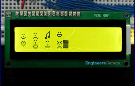
The commonly used 16×2 LCD can also display custom made characters besides numbers, alphabets & special characters. Any character can be made to appear on a 5×8 pixel matrix element without knowledge of its ASCII value. The idea explained here demonstrates the principle and operation of a simple LCD custom character display using 8051 microcontroller (AT89C51). When the ASCII code for any character, say ‘A’, is sent to be displayed on LCD module, the module’s controller looks up the appropriate 5×8-pixel pattern in ROM (read-only memory) and displays that pattern on the LCD. There are 8 symbol locations where a custom character can be stored as shown in the following right table. These locations will have a particular bitmap layout corresponding to the custom character. To display an arrow sign, the bitmap values are mapped to a base address location, say 64 (ASCII code 0).
How to program a microcontroller | How to burn a microcontroller
Programming or burning a microcontroller means to transfer the program from the compiler to the memory of the microcontroller. A compiler is a software which provides an environment to write, test and debug a program for the microcontroller. The program for a microcontroller is generally written in C or assembly language. Finally the compiler generates…
Difference between Microprocessor and Microcontroller
The term microprocessor and microcontroller have always been confused with each other. Both of them have been designed for real time applications. They share many common features and at the same time they have significant differences. Both the IC’s – i.e., the microprocessor and microcontroller – cannot be distinguished by looking at them. They are…
AT89S51/52 ISP Programmer – Lock Bits Setting
Lock bits are set of bits to enable or disable some special security features of a microcontroller. For example, in some cases you might want to disable the memory read functionality of the microcontroller, so that the code you have written cannot be stolen by others. The number of lock bits and their functionality is…
AT89S51/52 ISP Programmer – Memory Write
This tutorial explains how to write the content in the microcontroller’s flash memory. The source microcontroller writes some values in the memory of the target microcontroller. The values that have been written can be checked by reading the buffer of the target microcontroller using a programmer. The values are nothing but the machine language instruction…
AT89S51/52 ISP Programmer – Memory Read
This tutorial explains how to read the content of the microcontroller’s flash memory. The source microcontroller reads the content of the memory and displays it on the LEDs. The content is nothing but the program written in the memory of microcontroller. This step is often used to verify whether microcontroller has been correctly programmed or…
AT89S51/52 ISP Programmer – Signature Byte Read
The Signature Byte is a unique sequence of bytes which are used to identify the chip. It is written in the memory of the chip during the manufacturing process and cannot be changed. These memory locations are read only. Every chip manufactured by a company with the same number has the same signature byte.…
AT89S51/52 ISP Programmer – Erase
This is the first operation that needs to be performed on the target microcontroller. It is assumed that the target microcontroller has some code in its flash memory. If it does not has any content, write any program in the memory using a programmer. Whenever the flash memory of the chip is erased successfully,…
89S51/52 ISP Programmer – Basics
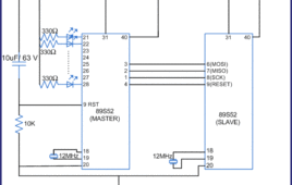
Everyone in their daily life has been using microcontrollers knowingly or unknowingly embedded in machines like cars, TV, refrigerator, washing machine, etc. Many of you know the capabilities of microcontrollers and have worked with it. You should have programmed it using different programmers by manufacturers. Have you ever thought how does a programmer work?…
Attendance Software using RFID Module
This application demonstrates a prototype attendance system using RFID and a software developed in C# .Net framework. The software interacts with the RFID reader through the serial port. The software has very limited functionalities. However it can be extended to a complex commercial application. The aim of this project is to show how RFID…
Microcontroller Programmer/Burner
A microcontroller programmer or microcontroller burner is a hardware device accompanied with software which is used to transfer the machine language code to the microcontroller/EEPROM from the PC. The compiler converts the code written in languages like assembly, C, java etc to machine language code (which is understandable by the machines/microcontrollers) and stores it in…
How to control Stepper Motor using ULN2003 and 8051 Microcontroller (AT89C51)- (Part 17/45)
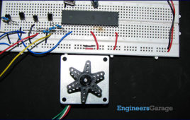
Stepper motor is a variable reluctance DC motor. When correct input sequence of signal is given to the motor, it starts rotation in steps. (For more detail refer Unipolar Stepper motor interfacing with microcontroller AT89C51). ULN2003 is high voltage, high current Darlington arrays each containing seven open collector Darlington pairs with common emitters. Here it…
How to interface Stepper Motor with 8051 Microcontroller (AT89C51)- (Part 16/45)
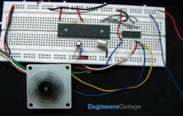
Stepper motor is one of the commonly used motors for precise angular movement. The advantage of using a stepper motor is that the angular position of the motor [[wysiwyg_imageupload::]]shaft can be controlled without any feedback mechanism. Stepper motors are widely used in industrial and commercial applications. They are also commonly used as in drive systems of autonomous robots.This article explains the unipolar stepper motor interfacing with AT89C51 microcontroller. The microcontroller is programmed to rotate the stepper in wave drive and half drive stepping modes. For basic concepts and working of a stepper motor, refer the article on Stepper Motors. A Unipolar Stepper Motor is rotated by energizing the stator coils in a sequence. In unipolar stepper, the direction of current in stator coils is not required to be controlled by the driving circuit. Just applying the voltage signals across the motor coils or motor leads in a sequence is sufficient to drive the motor.
How to display an image on Graphics LCD using AT89C52- (Part 45/45)
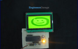
The Graphics LCD as the name suggests is a type of LCD which can display graphics. The graphical representation of any data presents good understanding thanjust characters. More user friendly applications can be designed by using the graphical LCDs. The graphical LCD can be used for advertisement boards or information boards and so on. This article explains the method of displaying image on a 128×64 graphical LCD using AT89C52. For basic operations and working, refer Graphics LCD interfacing with 8051. Microcontroller AT89C52 has been used to control the operations of the graphical LCD. The Graphics LCD used here is JHD12864E. This LCD is divided into two parts which are controlled by two different controllers. Each of these parts is divided into rows and columns. For basic instructions and programming procedure, refer to interfacing Graphics LCD with 8051. Also see displaying text on Graphics LCD. Read more to make interesting graphics on this florescent piece of display.


