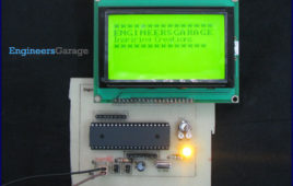
Simple operations with graphics LCD have been explained in the previous article. This article demonstrates the functionality of graphics LCD to display strings of [[wysiwyg_imageupload::]]different fonts. It explains the program to display strings in 8×8 and 5×7 fonts and also to scroll them vertically.The Graphics LCD used here is JHD12864E. This LCD is divided into two parts which are controlled by two different controllers. Each of these parts is divided into rows and columns. For basic instructions and programming procedure, refer to interfacing Graphics LCD with 8051.To display different font types, corresponding header files have been created. These header files contain the bitmap information of all alphabetic, numeric characters and symbols of a particular font. These header files are included into the main program. (The header file declarations are given in Code2).
How to interface Graphics LCD with 8051 Microcontroller (AT89C52)- (Part 43/45)
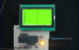
The graphical LCD used here is JHD12864E. This LCD is divided into two parts which are controlled by two different controllers. Each of these parts is divided into [[wysiwyg_imageupload::]]rows and columns.User friendly visual displays are used nowadays to keep track of working of any device. Such a visual display can be anything ranging from old Analog meters to new and smart Digital meters. In digital world to keep track of devices, LCDs are very commonly used. LCDs are easy to program and prove to be a better display unit as compared to other devices like seven segments and LED display units.The graphics LCDs are preferred over the character LCDs for those applications where both character and graphical representation are required. This article explains the basics of a 128×64 Graphics LCD and how it can be interfaced with AT89C52 to display basic shapes. The graphical LCD used here is JHD12864E. This LCD is divided into two parts which are controlled by two different controllers. Each of these parts is divided into rows and columns.To interface this LCD with microcontroller, two registers (Input and Output register) are provided in the LCD. These registers are selected by the combination of RS and RW signals.
How to interface GPS with 8051 Microcontroller (AT89C51)- (Part 36/45)
GPS has become an efficient tool in the field of scientific use, commerce, surveillance and tracking. This project presents a small application based onGlobal [[wysiwyg_imageupload::]]Positioning System. It depicts the use of GPS module/receiver to find latitude and longitude of its location. The data obtained from GPS receiver (GPGGA sentence) is processed by the microcontroller to extract its latitude and longitude values.The GPS Module has been interfaced with AT89C51 and the location values are displayed on a 16×2 LCD interface. The GPS module continuously transmits serial data (RS232 protocol) in the form of sentences according to NMEA standards. The latitude and longitude values of the location are contained in the GPGGA sentence (refer NMEA format). In this program, these values are extracted from the GPGGA sentence and are displayed on LCD.The serial data is taken from the GPS module through MAX232 into the SBUF register of 8051 controller (refer serial interfacing with 8051). The serial data from the GPS receiver is taken by using the Serial Interrupt of the controller.
How to extract details from GPS Receiver using 8051 Microcontroller- (Part 37/45)
This project is an extension to interfacing GPS with 8051. Here the microcontroller interfaced with GPS module is used to obtain latitude, longitude, time, date and [[wysiwyg_imageupload::]]speed of the receiver. These received values are displayed on a 16×2 character LCD.The GPS module continuously transmits serial data (RS232 protocol) in the form of sentences according to NMEA standards. The latitude, longitude, time, date and speed values of the receiver are contained in the GPRMC sentence as given in the following example (also refer NMEA format for other sentences). In this project, these values are extracted from the GPRMC sentence and are displayed on LCD.Example : $GPRMC,132455.970,A,2651.0145,N,07547.7051,E,0.50,342.76,301010,,,A*64The serial data is taken from the GPS module through MAX232 into the SBUF register of 8051 controller (refer serial interfacing with 8051). The serial data from the GPS receiver is taken by using the Serial Interrupt of the controller. This data consists of a sequence of NMEA sentences from which GPRMC sentence is identified and processed.
How to interface Humidity Sensor with 8051 Microcontroller (AT89C51)- (Part 31/45)
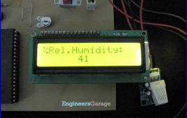
Humidity sensor works on the principle of relative humidity and gives the output in the form of voltage. This analog voltage provides the information about the percentage relative humidity present in the environment. The relative humidity is defined as: The analog output of sensor is connected to ADC to get its corresponding digital value.…
Servo Motor control through Keypad using 8051 Microcontroller (AT89C51)- (Part 20/45)
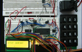
The basic operations of servo motor control have been discussed in interfacing servo with 8051. This project allows the servo motor to move to an angle specified [[wysiwyg_imageupload::]]by the user. The pulse train required to rotate the servo is produced by AT89C51 microcontroller. The desired angle of rotation is provided through a 4×3 keypad interfaced to the microcontroller. A 16×2 LCD is also connected with the microcontroller to display the angle of rotation entered by the user. For basic operations and control of servo motor, refer interfacing servo with 8051. The first pin of port P1 (P1^0) of AT89C51 microcontroller is set as the output pin to provide control signal to the servo motor. Ports P0 and P2 are used to interface keypad and data pins of LCD, respectively. Ports P1^3, P1^4 and P1^5 are connected to RS, RW and EN pins of LCD, respectively. Before connecting to the control wire of servo, the output from the microcontroller (P1^0) is fed through a comparator IC (LM324) so that the signal is protected from any loss due to overloading.
How to interface Servo Motor with 8051 Microcontroller (AT89C51)- (Part 19/45)
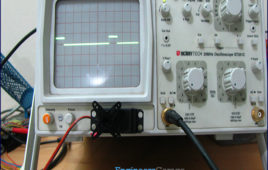
This project demonstrates the operation of a servo motor. The control signals for the rotation of the motor are provided by 8051 microcontroller (AT89C51). Here, [[wysiwyg_imageupload::]]the servo arm is rotated by 5° from the previous position, starting from 0 °as initial position. As the servo reaches a limit, the arm comes back to the initial position (0°). For basic concepts and know-how of a servo motor, refer to the article Servo Motor.The servo motor is controlled by feeding pulse width modulated (PWM) signal at the control wire of the servo motor. In addition a 4.8V (ideally 5V) DC supply is provided to the red lead of the servo. The black lead of the servo is connected to Ground. The first pin of port P1 (P1^0) of AT89C51 microcontroller is set as the output pin to provide control signal to the servo motor. Before connecting to the control wire of servo, the output from the microcontroller is fed through a comparator IC (LM324) so that the signal is protected from any loss due to overloading.
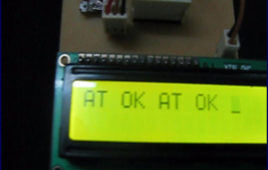
How to interface GSM Module with 8051 microcontroller (AT89C51) using PC- (Part 38/45)
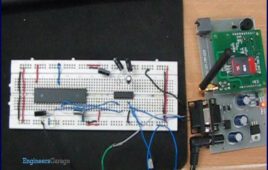
GSM is widely used mobile communication architecture used in most of the countries. This project demonstrates the interfacing of [[wysiwyg_imageupload::]]microcontroller AT89C51 with HyperTerminal and GSM module. It aims to familiarize with the syntax of AT Commands and their Information Response and Result Codes. The ASCII values of characters in the Information Response, Result Codes and their syntax can be monitored by an LED array. For the basic concepts, working and operation of AT commands and GSM module refer GSM/GPRS Module. The project explains interfacing of the AT89C51 microcontroller with the GSM module and the HyperTerminal. HyperTerminal is a Windows application. TheAT commands are sent by the HyperTerminal to the GSM module. The Information Response and/or Result Codes are received at the microcontroller and retransmitted to the HyperTerminal by the controller. Read on to understand how does this circuit work and how its microcontroller can be programmed.
How to interface GSM Module with 8051 microcontroller (AT89C51) using PC and LCD- (Part 39/45)
This project is an extension of interfacing microcontroller with hyperterminal and GSM module. The previous project explained a way to interface a GSM [[wysiwyg_imageupload::]]module with 8051 microcontroller where the information response and result codes received by the controller were sent back to computer to display them at HyperTerminal. In this project, the same output is displayed on a 16×2 LCD interface. This project is first step towards making and independent system using the GSM module and a microcontroller. Here the HyperTerminal (computer) has been replaced with LCD at the output end. In the next project (MC076), the AT Commands will be transmitted to the GSM module by the microcontroller itself thus avoiding the need of using HyperTerminal entirely. This project adds a feature to display the information response and result codes on a 16×2 LCD in response to the AT commands sent through the HyperTerminal of computer. The characters typed at HyperTerminal get transmitted serially through the transmit pin (Tx) of RS232 interface.
Interfacing GSM Module with 8051 microcontroller (AT89C51) without using PC- (Part 40/45)
This project presents a way to interface GSM module with microcontroller AT89C51 without making use of computer to send AT commands to the module. This is [[wysiwyg_imageupload::]]an improvement over the previous projects (see MC074 & MC075). Instead of using HyperTerminal or any other PC interface, the controller itself sends a fixed AT command to the GSM/GPRS module. The information response and result codes are received and displayed on a 16×2 LCD. Instead of sending commands from the HyperTerminal, AT commands are sent to the GSM/GPRS module by the microcontroller itself. In this case, the receive (Rx) and transmit (Tx) pin of the GSM module’s RS232 port are connected to the transmit (Tx) and receive (Rx) pin of AT89C51’s serial port, respectively. This eliminated the role of computer and just the controller’s circuit provides a complete user interface for the module. Read more to reveal the connections and the working of this 8051 based electronic project.
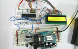
How to Reset EEPROM (24C02) Memory using 8051 microcontroller- (Part 42/45)
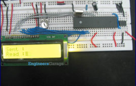
AT24C02 is two-wire serially programmable EEPROM. This means that for programming, the data and control signals are provided serially along with clock signals from the other wire. The read-write operations are accomplished by sending a set of control signals including the address and/or data bits from a microcontroller. This project demonstrates the memory reset operation of a 24C02 IC by using AT89C51. For basic operations of AT24C02, refer interfacing serial EEPROM with 8051. It writes & reads a byte to/from the EEPROM displaying it on a 16×2 LCD, and then resets the memory. The results can be monitored on the LCD display.AT24C02 is a two-wire serial EEPROM from Atmel. 24C02 is an 8 pin IC and reads 8 bit data serially. Its memory size is 2KB. Pins 1- 3 are address pins which are connected to ground. Pin 4 is GND; Pin 5 is SDA (serial data); and pin 6 is SCL (serial clock input). Pin 7 is WP (write protect) pin and is connected to GND. Pin 8 is Vcc for providing power supply.
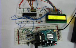
How to Interface Serial EEPROM 24C02 with 8051 microcontroller (AT89C51)- (Part 41/45)
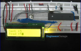
EEPROM stands for electrically erasable programmable read only memory. It is a secondary storage device that once written (programmed) can hold data even [[wysiwyg_imageupload::]]when the power is removed. The EEPROM is a class of read only memory that can be electrically erased and reprogrammed.AT24C02 is a two wire 2Kbits serial EEPROM by Atmel. The memory is organized in 256 words of single byte each arranged in 32 pages of 8 bytes each. The addressing of memory locations requires eight bit addresses.AT24C02 is two-wire serially programmable i.e., for programming, the data and control signals are provided serially along with clock signals from the other wire. The read-write operations are accomplished by sending a set of control signals including the address and/or data bits. The control signals must be accompanied with proper clock signals.The AT24C02 has hard wire addressing of 3 bit length. This facilitates interfacing of a maximum of eight (23) 24C02 devices to a system thereby, incorporating a maximum 16Kbits memory. Multiple 24C02 devices can be connected to a microcontroller/microprocessor based system using I2C interface.
Toll plaza system based on vehicle category using 8051 microcontroller (AT89C51)
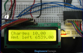
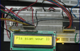
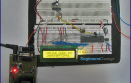
This topic is an extension to Simple toll plaza system. The toll amount is charged based on the category of the vehicle driving through the plaza. The vehicle categories taken here are two-wheeler & four-wheeler. When a user scans his ID at the toll plaza, some amount is charged from his account depending upon his vehicle category. User also has the facility to recharge his account.The project has been developed by interfacing RFID with AT89C51. The relevant messages are also displayed on a 16×2 LCD. The free source code for the program is available in C.Simple toll plaza system charges the toll tax from the user irrespective of the type of his vehicle. This project also considers the vehicle type while charging the toll amount. The RFID tag is used as a unique identity for account of a particular user. When a vehicle drives through the toll plaza, its driver is prompted to scan his RFID tag. If the identity (serial number of the tag, i.e., 12 byte data) is matched with the one already stored in the system, the toll amount is deducted from his account. After this, the vehicle gets immediate access to drive through. All the features of the Simple toll plaza system are also provided in this project by interfacing RFID with AT89C51.
Simple toll plaza system using low frequency RFID interfaced with 8051 microcontroller (AT89C51)
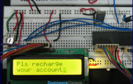
Electronic/automated toll collection systems are very popular these days. They do not require manual collection and operation of toll barriers. The details about [[wysiwyg_imageupload::]]the vehicles and payment are stored in an RFID based system.This article explains the working of a simple toll plaza system interfaced with RFID. Each user holds a unique ID for his vehicle. When the user scans his tag while passing through the plaza, a certain amount is deducted from his account. A user may also recharge his account in case of insufficient balance. The project has been developed by interfacing RFID with AT89C51. The relevant messages are also displayed on a 16×2 LCD. The free source code for the program is available in C.Low frequency RFID work at 125 KHz frequency with radio waves. There is a coil inside the RFID tag and when it is influenced by a magnetic field, it sends a 12 byte identity code to RFID reader for further processing. The RFID tag is used as a unique identity for account of a particular user. When a vehicle drives through the toll plaza, its driver is prompted to scan his RFID tag. If the identity (serial number of the tag, i.e., 12 byte data) is matched with the one already stored in the system, the toll amount is deducted from his account. After this, the vehicle gets immediate access to drive through.
RFID based Secured access system using 8051 microcontroller (AT89C51)
Low frequency RFID works on the principle of radio waves and at the frequency of 125 KHz. There is a coil inside the RFID tag and when it is influenced by magnetic field, it sends an identity code to a device for further processing. (For more details, refer interfacing RFID with AT89C51). The RFID…
Interfacing RFID with 8051 microcontroller (AT89C51) using serial interrupt- (Part 35/45)
This topic covers the interfacing of RFID system with microcontroller through serial interrupt. An RFID system consists of a reader device and a transponder. A transponder or tag has a unique serial number which is identified by the reader. RFID tag is applied to products, individuals or animals to identify and track them through this number. The interfacing has been…
How to interface RFID with 8051 microcontroller (AT89C51)- (Part 34/45)
An RFID (Radio-frequency identification and detection) reader is a device which is used to communicate with RFID tags by receiving and transmitting signals. These signals use radio waves for wireless communication. RFID tag is applied to products, individuals or animals to identify and track them. The identification is done through a unique serial number. This topic covers the…
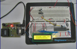
Digital clock using DS12C887 and 8051 microcontroller (AT89C51) in 12 hour mode

This article is an improved version of LCD based clock using RTC DS12C887 and 8051 microcontroller (AT89C51) using update interrupt. DS12C887 has two modes of operation i.e., 12 hour and 24 hour mode. In our earlier articles we explained how to use 24 hour mode. This article explores how we can use the 12 hour mode of RTC. This is done by making a clock using RTC and 8051 microcontroller (AT89C51) with 12 hour mode operation. The clock time is displayed on a 16×2 LCD interface. The free source code for the program is available in C.Port P2 is used as data port for LCD while port P0 of the microcontroller AT89C51 is used as data port for the RTC DS12C887. The pins P1^0 – P1^7 of the microcontroller are configured as reset, rs, rw, e, dig_hr1, dig_min1, start, setmode, am_pm pins respectively.
Clock using RTC DS12C887 & 8051 microcontroller (AT89C51) with alarm set function
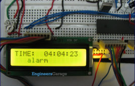
DS12C887 is a real time clock (RTC) IC from Dallas Semiconductors. The RTCs provide precise time and date information. This article explains the making of a [[wysiwyg_imageupload::]]digital clock with alarm setting functionalities. RTC has been interfaced with AT89C51 to perform desired operations. This project is an improvement over Digital clock using RTC DS12C887 and 8051 microcontroller (AT89C51) with time set and has the alarm setting function also. The alarm setting function allows user to set the alarm. The clock time is displayed on the LCD. The free source code for the program is available in C.The circuit for interfacing the RTC and 16×2 LCD with the microcontroller 8051 is shown in the circuit diagram. Port P2 is set as data port for LCD to send the data on the LCD while port P0 is set as data port for the RTC DS12C887.
Digital clock using RTC DS12C887 and 8051 microcontroller (AT89C51) using update interrupt
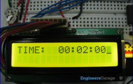
This article is an improved variant of Digital clock using RTC DS12C887 and 8051 with time set. In the earlier article, we discussed the basics of extracting data from [[wysiwyg_imageupload::]]the RTC DS12C887 using the 8051 microcontroller (AT89C51). This article is in continuation to the above article and introduces you to the concept of handling interrupts for extracting time and other information from the RTC.Interrupts offer a great flexibility to handle RTC. Interrupts have several advantages over the method of polling as discussed in the previous article. It reduces the unnecessary usage of microcontroller’s memory and processing powers, thereby keeping the processor free for other use. RTC 12C887 has three interrupts, namely, Alarm interrupt, Periodic interrupt & Update ended interrupt. For detailed information, check RTC interrupts. The free source code for the program is available in C.This article assumes that the user is aware of real time clock and the basic interfacing of DS12C887 with 8051 microcontroller (AT89C51) including the pin description, memory and registers of RTC DS 12C887.