Many devices require input pulses for their operation. Some device requires continuous train of pulses some requires single pulse. In some of the devices there is a provision to alter between continuous pulses and single pulse. For example a stepper motor controller can have two operating modes – auto and manual. In auto mode it requires continuous pulses to rotate motor continuously while in manual mode it requires single pulse to be generated when button is pressed manually.
The circuit presented here is 2 in 1 circuit that generates low frequency pulses in the output. It has two operating modes. In auto mode it generates pulses continuously and in manual mode it generates pulse when push button is pressed. The circuit is built using single IC555. To generate continuous pulses it is configured in astable mode and to generate single pulse it is configured in monostable mode.
[[wysiwyg_imageupload:12830:]]
Fig. 1: Prototype of Auto and Manual Pulse Generator Circuit using single IC555 on Breadboard
Circuit connections:
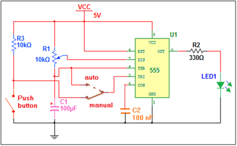
The circuit is made up around IC555. It uses few other components like resistors, pot, capacitor, sliding switch, push button and LED.
· One 10 K pot R1 is connected between Vcc and pin no. 6. Its sliding terminal is connected to pin no. 7 as shown
· A 100 µF capacitor C1 is connected between pin no. 6 and ground.
· R1 and C1 are timing components
· Pin no. 2 can be connected to pin no 6 or it can be connected to push button through sliding switch as shown
· Output pin 3 drives LED through current limiting resistor R2
· Pin 8 is connected to Vcc and pin 1 is grounded to provide bias
· Pin 4 is connected to Vcc to enable circuit operation
· Pin 5 is grounded through 100 nF capacitor C2
Figure given below shows snap of circuit built on bread board
Circuit operation:
Auto mode:
For auto mode move sliding switch position to auto. This will short pin 6 and pin 2. Turn pot R1 to somewhere in the middle. So there will be some resistance between pin 6 and pin 7. This makes IC555 to be configured in astable mode. When supply is given the circuit will start generating low frequency (<1 Hz) pulses. This can be observed as LED blinking
Manual mode:
For manual mode move sliding switch position to manual. This will connect pin 2 with push button. Turn pot R1 fully towards pin 6. So the resistance between pin 6 and 7 will be zero – that means they are now short. This makes IC555 to be configured in monostable mode. Connect the supply to circuit and press push button. Short pulse is generated that is indicated by LED. Every time push button is pressed pulse is generated and LED glows.
Circuit Diagrams
Project Components
Project Video
Filed Under: 555 Timers, Electronic Projects
Filed Under: 555 Timers, Electronic Projects

Questions related to this article?
👉Ask and discuss on EDAboard.com and Electro-Tech-Online.com forums.
Tell Us What You Think!!
You must be logged in to post a comment.