Summary:
In this Project, we are going to build a circuit used to measure unknown resistance. When we connect any resistor in the breadboard circuit the exact value of the resistor is displayed in the 16×2 LCD. This is done by utilizing the ADC feature of the Arduino and the voltage divider concept to measure the resistance with reduced errors. Now-a-days we use multimeter with range selector switches to find the unknown resistance which will consume time, so we also introduced Auto ranging feature to reduce the manual ranging functions by implementing logics in coding and hardware which is discussed below.
Description:
Hardware assembly:
The entire project can be divided into three basic blocks;
1) Auto ranging Resistance Sensor Unit
2) Processor Unit
3) Display Unit

Fig. 1: Block Diagram of Arduino based Auto Ranging Ohm Meter
Auto ranging Resistance Sensor Unit:
A basic voltage divider circuit is used as the Resistance Sensing Unit to provide an output, which is the voltage equivalent of the unknown resistor as the input. From this output voltage we can calculate the value of unknown resistance, detect the diode type or detect a continuous path. For more details you can refer here.
A scheme for estimating the value of unknown resistance value roughly and then altering the matching resistor in place of R2 is what we need here and this is called auto ranging. The circuit given below demonstrates auto ranging.
Arduino resistance meter Resistances R1 to R7 are the input resistors. Here in an instance of time the free end of one resistor is held high and the free ends of other resistors are held low. Then the voltage across the unknown resistance Rx is measured. Diodes are used to prevent the back flow of current from the lower ends. Suppose free end of R1 is held high. If the voltage across Rx is less than or equal to R1 then, the voltage drop across Rx will be less than or equal to (5-0.7)/2 = 2.15 where 0.7 is the diode drop. we can assume that Rx is less than or equal to 120 ohms and vice versa. The above steps are repeated with the succeeding input resistors until we get a solution. The closest value possible for the input resistance is 120 ohms and so this loop is considered for calculation.
Full circuit diagram of the auto ranging ohmmeter used Arduino is shown in the figure above. Pins 10, 11, 12, 13, A0, A1, A2 of the Arduino is used to switch the input resistors R1, R2, R3, R4, R5, R6, R7 respectively. Diodes D1 to D7 are used to prevent the back flow of current through the corresponding path.
Processor unit:
The processor unit in this project is the Arduino board and it uses the ADC module to read the output voltage from the Sensor Unit. On the Arduino board, we are using an 8 channel, 10 bit ADC with the reference voltage pin connected to 5 V. The ADC reads the voltage V2 and generates an equivalent value ‘ValueADC‘at the ADC register. For more details refer this link.
Display Unit:
The display unit in this project uses a common 16*2 LCD on which the Arduino displays the resistor value and diode type. The LCD has been wired in four bit mode to reduce the number of output pins of the Arduino. The code running on the Arduino used the library function analogRead() to obtain the ADC value and lcd.print() to display the data on 16*2 LCD.

Fig. 2: Prototype of Arduino based Auto Ranging Ohm Meter designed on a breadboard
Circuit Diagrams
| Image-Showing-Resistor-Network-Interfaced-Arduino-Measuring-Resistance | 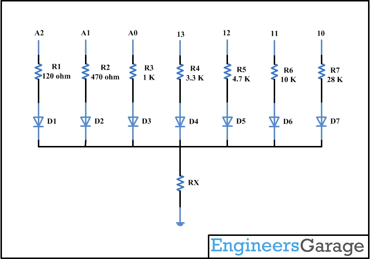 |
| Circuit-Diagram-Arduino-Based-Auto-Ranging-Ohm-Meter | 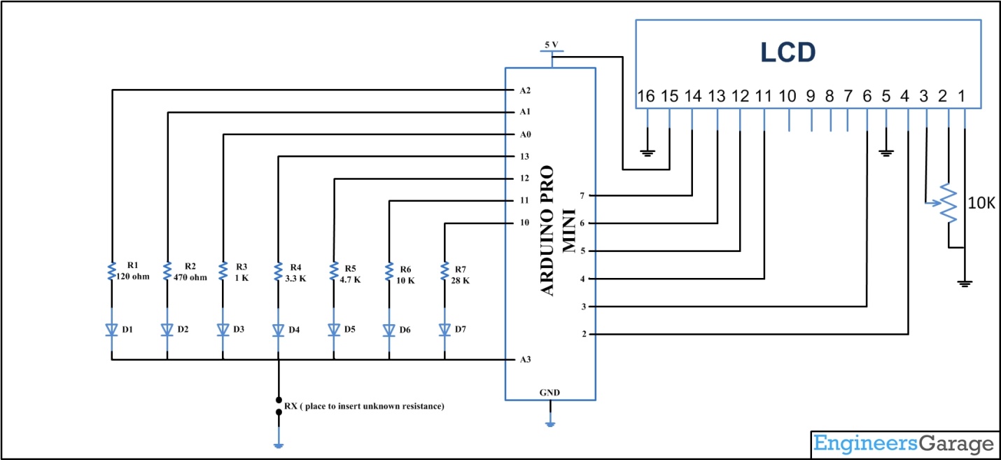 |
Filed Under: Electronic Projects

Questions related to this article?
👉Ask and discuss on EDAboard.com and Electro-Tech-Online.com forums.
Tell Us What You Think!!
You must be logged in to post a comment.