Engineers Garage

  • Projects and Tutorials
    • Electronic Projects
      • 8051
      • Arduino
      • ARM
      • AVR
      • PIC
      • Raspberry pi
      • STM32
    • Tutorials
    • Circuit Design
    • Project Videos
    • Components
  • Articles
    • Tech Articles
    • Insight
    • Invention Stories
    • How to
    • What Is
  • News
    • Electronic Products News
    • DIY Reviews
    • Guest Post
  • Forums
    • EDABoard.com
    • Electro-Tech-Online
    • EG Forum Archive
  • Digi-Key Store
    • Cables, Wires
    • Connectors, Interconnect
    • Discrete
    • Electromechanical
    • Embedded Computers
    • Enclosures, Hardware, Office
    • Integrated Circuits (ICs)
    • Isolators
    • LED/Optoelectronics
    • Passive
    • Power, Circuit Protection
    • Programmers
    • RF, Wireless
    • Semiconductors
    • Sensors, Transducers
    • Test Products
    • Tools
  • EE Resources
    • DesignFast
    • LEAP Awards
    • Oscilloscope Product Finder
    • White Papers
    • Webinars
  • EE Learning Center
  • Women in Engineering

Automated Car Lightning System

By Disha Karnataki

Summary:

In an effort to improve road safety Government has rolled out a new regulation as per which, if a vehicle is approaching from the opposite side, one is required to dim out the headlights so that it doesn’t cause any trouble to the driver who is approaching from the other side. This would help in avoiding a lot of accidents.
However, if this dimming and brightening of headlights is made an automatic function then it could help to ensure a safe drive as well as a convenient driving experience.

Description:

Block diagram:

Block Diagram of Automatic Car Headlights

Fig. 1: Block Diagram of Automatic Car Headlights

Description:

LDR sensor:

LDR stands for Light Dependant Resistor.  It acts as a variable resistor whose resistance changes with the intensity of light..When the light intensity increases, the resistance offered by the sensor decreases and vice versa.
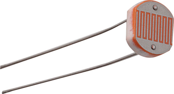
 

Typical Image of Light Dependant Resistor (LDR) used as Light Sensor in the circuit

Fig. 2: Typical Image of Light Dependant Resistor (LDR) used as Light Sensor in the circuit

Circuits and Working

Sensing Circuit

This is made to work as a switch making transistor to operate in saturation and cut off region. Here LDR provides necessary bias to the transistor.
Components used:
1)LDR sensor
2)60kohm resistor
3)IRFZ44N transistor (or any n channel MOSFET)
4)relay
5)connecting wires
6)supply 12V from car batteries
All componenets are self explanatory.

I have  preferred IRFZ44N because of high current and good heat dissipation capability.

Relay :
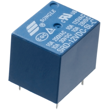
Typical Image of Relay used for switching Headlights

Fig. 3: Typical Image of Relay used for switching Headlights

This has NC (normally Closed) & NO (Normally Opened) contacts.
Out of this, “NC” contact is used where bright light of the headlight is connected.
“NO” contact is used where dim light of the headlight is connected.
Reason is explained after circuit diagram’s description.
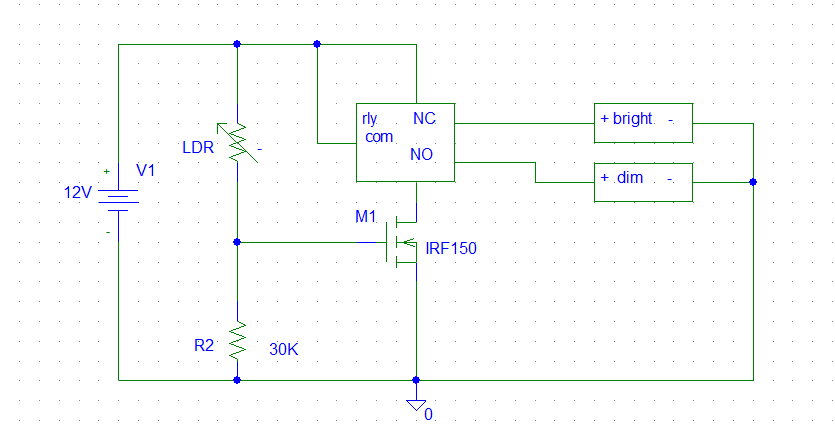
CIRCUIT DIAGRAM:
There are two headlights, one is dim another is bright.  If you cannot distinguish well between these then you may ask the garage people to fix that as there are different arrangements for different cars.
The LDR should be exposed to light hence it must be placed in a way that the lights of the opposite car approaching you must fall on the LDR and not on your own car’s lights.
Although resistor 30K suits for my circuit, one may take exact MOSFET.  Due to manufacturing process one transistor cannot be exactly identical  to the other (their beta value may change).Hence 30K value cannot be assured for your circuit so make adjustments such that transistor acts as a switch for the considered resistor values.

Working:

When light shines on LDR its resistance decreases and hence bias voltage of the MOSFET increases turning it on and hence relay status changeover takes place from NC TO NO. As there is dim bulb connected to NO it turns on. Similarly as the car passes by, light ceases to fall on LDR and hence its resistance increases which causes a lower Vbe MOSFET voltage thereby switching off the transistor. Relay status changeover takes place from NO to NC and thus bright bulb switches are turned on.
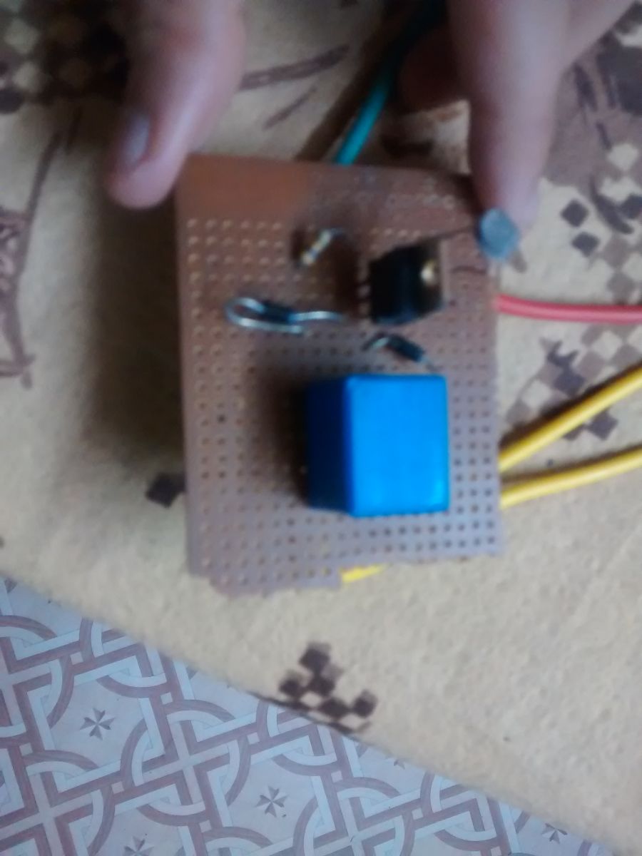
Prototype of Relay Circuit soldered on a PCB for automatic controlling of car headlights
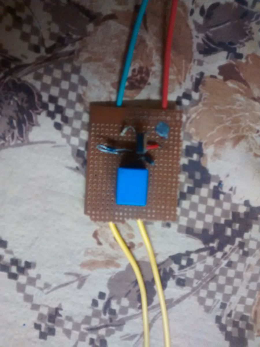
Fig. 4: Prototype of Relay Circuit soldered on a PCB for automatic controlling of car headlights

Image showing wiring of relay circuit for automatic controlling of car headlights

Fig. 5: Image showing wiring of relay circuit for automatic controlling of car headlights
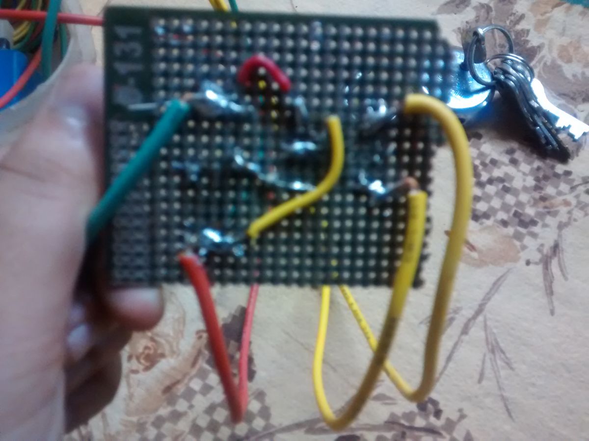
Image showing soldering of relay circuit

Fig. 6: Image showing soldering of relay circuit

Circuit Diagrams

Circuit-Diagram-Electronic-Circuitry-Used-Automatic-Car-Headlights


Filed Under: Circuit Design, Electronic Projects


Questions related to this article?
👉Ask and discuss on EDAboard.com and Electro-Tech-Online.com forums.


Tell Us What You Think!! Cancel reply

You must be logged in to post a comment.

HAVE A QUESTION?

Have a technical question about an article or other engineering questions? Check out our engineering forums EDABoard.com and Electro-Tech-Online.com where you can get those questions asked and answered by your peers!


Featured Tutorials

  • Designing Gate Driver Circuit and Switching Mechanism for Modified Sine Wave Inverter – (Part 9/17)
  • Completing Modified Sine Wave Inverter Design with Full Bridge Circuit and Step Up Transformer – (Part 10/17)
  • Designing an Offline UPS – Part (12 /17)
  • How to reduce Switching Time of a Relay – (Part 15/17)
  • Testing MOSFET – (Part 16/17)
  • Driving High Side MOSFET using Bootstrap Circuitry – (Part 17/17)

Stay Up To Date

Newsletter Signup

Sign up and receive our weekly newsletter for latest Tech articles, Electronics Projects, Tutorial series and other insightful tech content.

EE Training Center Classrooms

EE Classrooms

Recent Articles

  • Designing Gate Driver Circuit and Switching Mechanism for Modified Sine Wave Inverter – (Part 9/17)
  • Completing Modified Sine Wave Inverter Design with Full Bridge Circuit and Step Up Transformer – (Part 10/17)
  • Designing an Offline UPS – Part (12 /17)
  • How to reduce Switching Time of a Relay – (Part 15/17)
  • Testing MOSFET – (Part 16/17)

Most Popular

5G 555 timer circuit 8051 ai Arduino atmega16 automotive avr dc motor display Electronic Part Electronic Parts Fujitsu ic infineontechnologies integratedcircuit Intel IoT ir lcd ldr led maximintegratedproducts microchip microchiptechnology Microchip Technology microcontroller microcontrollers mosfet motor powermanagement Raspberry Pi remote renesaselectronics Research robot samsung semiconductor sensor software STMicroelectronics switch Technology vishayintertechnology wireless

RSS EDABOARD.com Discussions

  • Please help to identify the signal input port on board
  • Hotplugging UART
  • RF switch selection
  • sensitivity in filters and number of bits of system
  • MDO4104-6 Front Panel Not Working

RSS Electro-Tech-Online.com Discussions

  • software PWM
  • Combination of Wires of two DC motor giving Output current.
  • Passthrough charging-simple but impossible to achieve?
  • geared motor to revolve oval platform
  • None existant errors (MPLAB X)
Engineers Garage
  • Analog IC TIps
  • Connector Tips
  • DesignFast
  • EDABoard Forums
  • EE World Online
  • Electro-Tech-Online Forums
  • Microcontroller Tips
  • Power Electronic Tips
  • Sensor Tips
  • Test and Measurement Tips
  • 5G Technology World
  • About Us
  • Contact Us
  • Advertise

Copyright © 2022 WTWH Media LLC. All Rights Reserved. The material on this site may not be reproduced, distributed, transmitted, cached or otherwise used, except with the prior written permission of WTWH Media
Privacy Policy | Advertising | About Us

Search Engineers Garage

  • Projects and Tutorials
    • Electronic Projects
      • 8051
      • Arduino
      • ARM
      • AVR
      • PIC
      • Raspberry pi
      • STM32
    • Tutorials
    • Circuit Design
    • Project Videos
    • Components
  • Articles
    • Tech Articles
    • Insight
    • Invention Stories
    • How to
    • What Is
  • News
    • Electronic Products News
    • DIY Reviews
    • Guest Post
  • Forums
    • EDABoard.com
    • Electro-Tech-Online
    • EG Forum Archive
  • Digi-Key Store
    • Cables, Wires
    • Connectors, Interconnect
    • Discrete
    • Electromechanical
    • Embedded Computers
    • Enclosures, Hardware, Office
    • Integrated Circuits (ICs)
    • Isolators
    • LED/Optoelectronics
    • Passive
    • Power, Circuit Protection
    • Programmers
    • RF, Wireless
    • Semiconductors
    • Sensors, Transducers
    • Test Products
    • Tools
  • EE Resources
    • DesignFast
    • LEAP Awards
    • Oscilloscope Product Finder
    • White Papers
    • Webinars
  • EE Learning Center
  • Women in Engineering