Summary:
Description:
Block diagram:
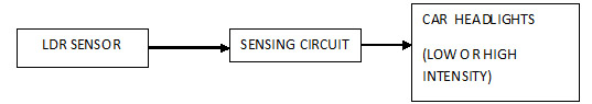
Fig. 1: Block Diagram of Automatic Car Headlights
Description:
LDR sensor:
LDR stands for Light Dependant Resistor. It acts as a variable resistor whose resistance changes with the intensity of light..When the light intensity increases, the resistance offered by the sensor decreases and vice versa.
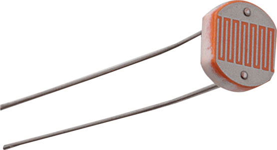
Fig. 2: Typical Image of Light Dependant Resistor (LDR) used as Light Sensor in the circuit
Circuits and Working
Sensing Circuit
I have preferred IRFZ44N because of high current and good heat dissipation capability.
Relay :
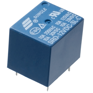
Fig. 3: Typical Image of Relay used for switching Headlights
Working:
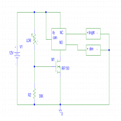
When light shines on LDR its resistance decreases and hence bias voltage of the MOSFET increases turning it on and hence relay status changeover takes place from NC TO NO. As there is dim bulb connected to NO it turns on. Similarly as the car passes by, light ceases to fall on LDR and hence its resistance increases which causes a lower Vbe MOSFET voltage thereby switching off the transistor. Relay status changeover takes place from NO to NC and thus bright bulb switches are turned on.
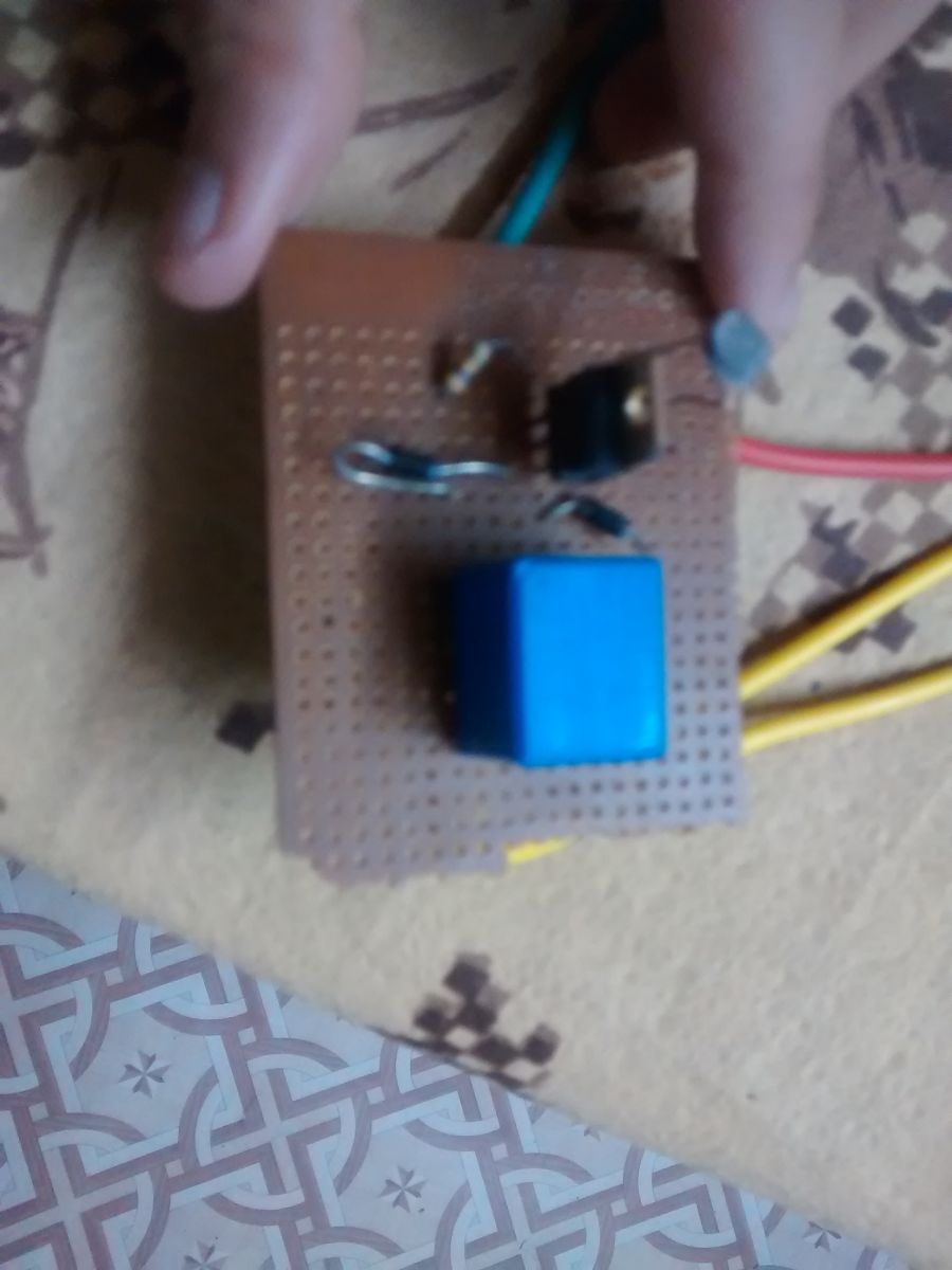
Fig. 4: Prototype of Relay Circuit soldered on a PCB for automatic controlling of car headlights
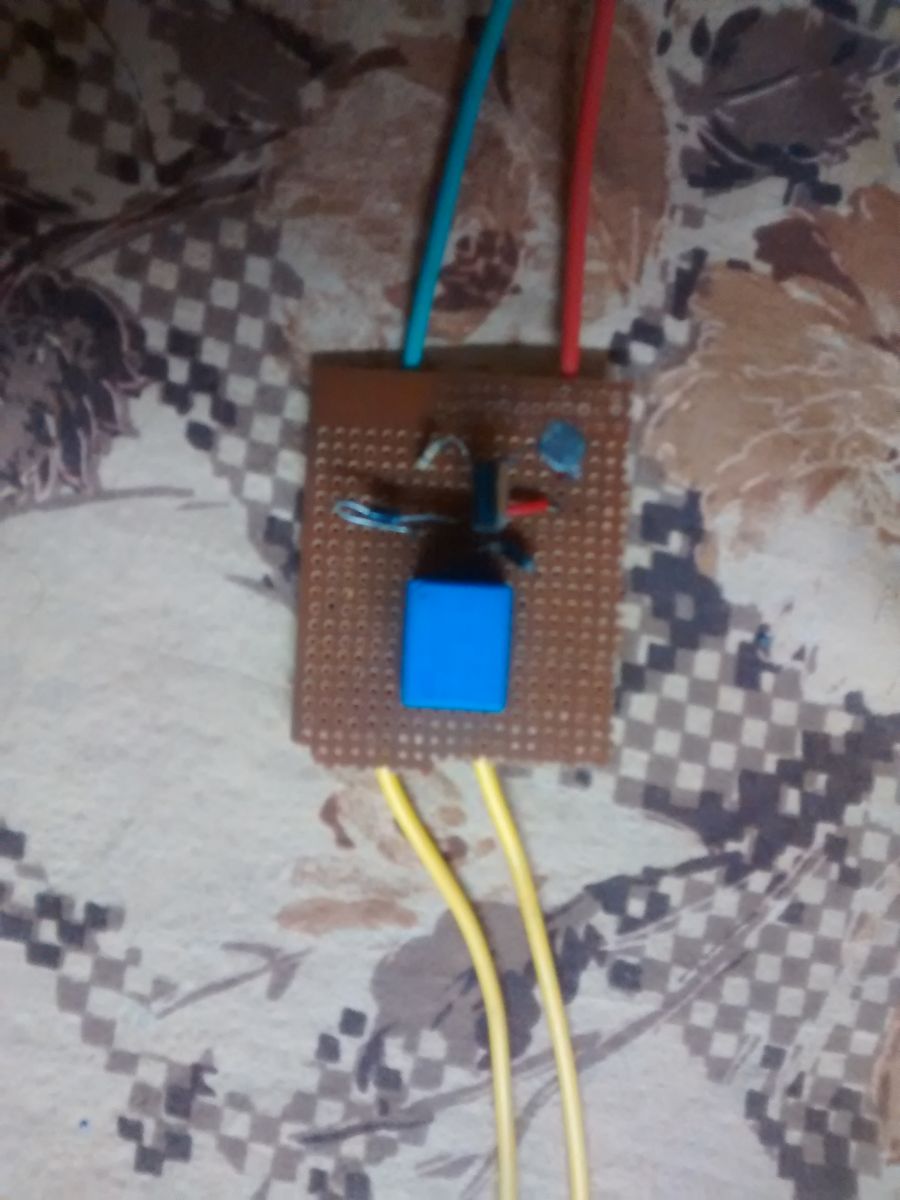
Fig. 5: Image showing wiring of relay circuit for automatic controlling of car headlights
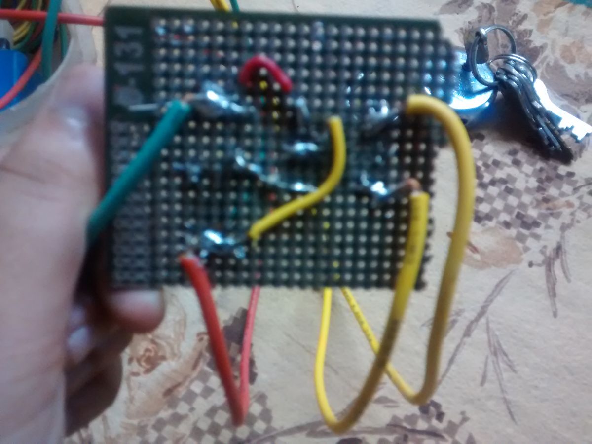
Fig. 6: Image showing soldering of relay circuit
Circuit Diagrams
Filed Under: Electronic Projects

Questions related to this article?
👉Ask and discuss on EDAboard.com and Electro-Tech-Online.com forums.
Tell Us What You Think!!
You must be logged in to post a comment.