Automatic door locks are becoming popular in industry and many companies are using them to protect their valuables. In offices and homes automatic door locks systems are used for the safety of rooms and to allow only authorized persons to enter the office. Automatic door lock systems are also popular in banks. Banks use automatic lock systems to keep security of their money stored in their vault. Others industries which heavily uses automatic door lock systems are also used in hotels,airports prison areas, hospitals and in homes.
89c51 Microcontroller Digital door lock working principle
In this project i am going to design a simple automatic door lock system using 8051(89c51,89c52) microcontroller, 16×2 lcd, 4×4 numeric keypad and a digital lock. In our diy digital lock system 8051(89c51,89c52) is our intelligent unit. All the processing’s will be done by 8051 microcontroller. Predefined/hard-coded password is downloaded in the code. User have to enter the code. If the code matches the predefined/hard-coded code lock will open up and user can enter the room. All the messages to “Input password”, “Access Granted”, “Access Denied” will be popping up on 16×2 lcd on the right time.
Note: A numeric password is hard coded in the 8051 microcontroller code.
Note: A numeric password is hard coded in the 8051 microcontroller code.
Door lock with 8051 microcontroller-Project requirements
- 8051(89c51,89c52) microcontroller
- 16×2 lcd
- 4×3 numeric keypad
- Lock system
- crystal (11.0592 MHz)
- Bread board(on which circuit is designing)
- Reset circuitry(capacitor(10 uf) and resistor(8.2 K ohm))
- Power supply
Door lock with 89c51 microcontroller – Circuit diagram
Character 16×2 lcd is interfaced in 8-bit mode with 89c52 microcontroller. Connect Port-1 of 89c52 microcontroller to the data pins of 16×2 lcd. Connect Port-3 pin-5 to rs(register select) pin of lcd. Connect Port-3 pin–6 to en(enable) pin of 16×2 lcd. Connect Port-3 pin-7 to rw(read-write) pin of 16×2 lcd. Attach your lock to Port-3 pin-0. The lock designing is explained after the door lock circuit diagram. 4×3 Keypad is attached to port-2 of 8051 microcontroller. Keypad rows are attached to Port-2 pins(0,1,2,3) and coulombs to pins(5,6,7). Other connections are for driving the microcontroller. Connect crystal with pins 18 and 19. Ground pin 20. Apply 5 volts to pins 40 and 31. Attach your reset circuitry to pin 9.
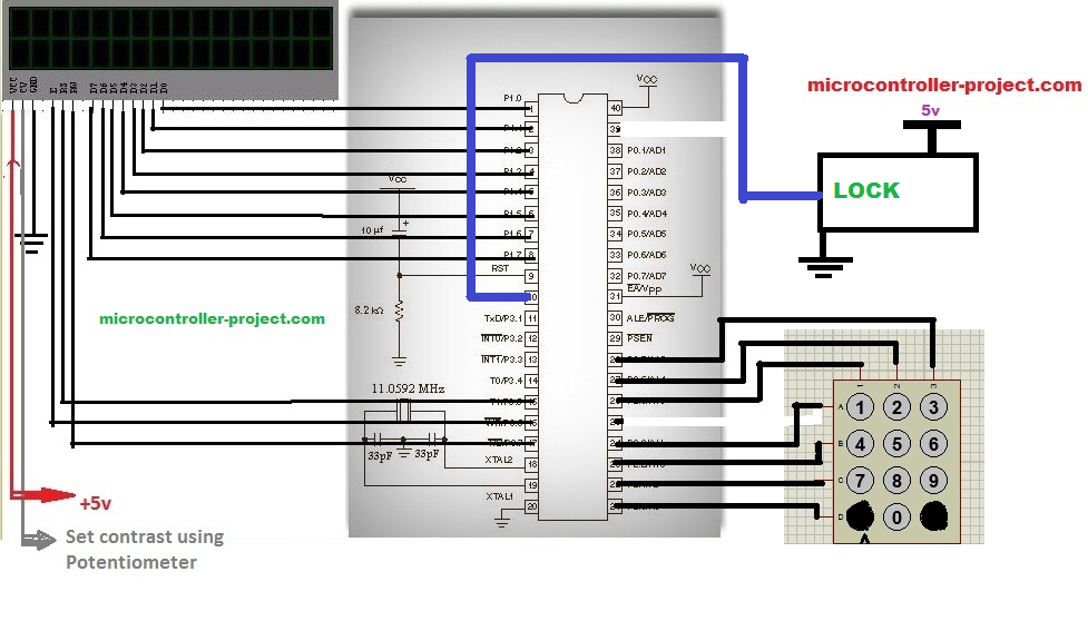
Automatic door lock system with 8051(89c51,89c52) Microcontroller-Circuit diagram
Door lock system
The lock system is some thing challenging but it is not as much hard to design as it look likes. I could not find any lock from market that works on TTL 5v. So i made a custom lock by my self. Its not that much fancy but its good as a diy project. You can see the lock circuit diagram below.
A small dc motor is attached to the transistor at the source. Dc motor is operating on 9 volts. Transistor gate is connected to port 3 pin 0. So when the user inputs the correct password the transistor becomes on and our dc motor rotates and move back lock needle, which opens the lock. To lock the door again manually pull up the lock needle.
A small dc motor is attached to the transistor at the source. Dc motor is operating on 9 volts. Transistor gate is connected to port 3 pin 0. So when the user inputs the correct password the transistor becomes on and our dc motor rotates and move back lock needle, which opens the lock. To lock the door again manually pull up the lock needle.
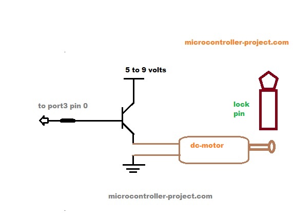
Lock circuitry
8051 microcontroller door lock code
The code is simple and easy to understand it is written in c language. First of all the necessary header file reg51.h is included. This header file must be included in every project made using keil as the software tool to write the code. Then the keypad rows and coulombs are declared. 16×2 lcd controlling pins and lock controlling pin is defined. All the upper described pins are declared individually because they are used in our code individually. Data pins for lcd are not defined because whole port1 is dedicated for data pins of lcd, and data is send parallel in 8-bit form.
Then some character arrays are defined. These character arrays contains the messages that are displayed on the 16×2 lcd when every certain condition is met or their is some wrong input.The password is manually set in the code it is “1234“. You can change it according to your desire but be sure that the password length should not be greater than 4 characters. The lock controlling pin is also defined as lock at Port-3 pin-0.
Functions used in door lock code
- void delay() Generating variable delay.
- void cmd() Sending commands to 16×2 lcd.
- void lcddata() Sending data to 16×2 lcd.
- void lcdint() Initializes 16×2 lcd.
- char keypad() Scaning keypad keys and taking input from user.
- void main() Main function.
Download the project files, Full code(C++) & hex file compiled in keil uvision 2. The folder also contains the simulation of the project. Simulation is made in proteaus 8.0. If you have any questions regarding project and code, please give me your feed back. You can also upgrade the code like set the password from taking input from the user. Make password length variable. Its very easy if you are keen to do it and you know c++ programming tactics.
Filed Under: 8051 Microcontroller., Microcontroller Projects

Questions related to this article?
👉Ask and discuss on EDAboard.com and Electro-Tech-Online.com forums.
Tell Us What You Think!!
You must be logged in to post a comment.