Engineers Garage

  • Projects and Tutorials
    • Electronic Projects
      • 8051
      • Arduino
      • ARM
      • AVR
      • PIC
      • Raspberry pi
      • STM32
    • Tutorials
    • Circuit Design
    • Project Videos
    • Components
  • Articles
    • Tech Articles
    • Insight
    • Invention Stories
    • How to
    • What Is
  • News
    • Electronic Products News
    • DIY Reviews
    • Guest Post
  • Forums
    • EDABoard.com
    • Electro-Tech-Online
    • EG Forum Archive
  • Digi-Key Store
    • Cables, Wires
    • Connectors, Interconnect
    • Discrete
    • Electromechanical
    • Embedded Computers
    • Enclosures, Hardware, Office
    • Integrated Circuits (ICs)
    • Isolators
    • LED/Optoelectronics
    • Passive
    • Power, Circuit Protection
    • Programmers
    • RF, Wireless
    • Semiconductors
    • Sensors, Transducers
    • Test Products
    • Tools
  • EE Resources
    • DesignFast
    • LEAP Awards
    • Oscilloscope Product Finder
    • White Papers
    • Webinars
  • EE Learning Center
  • Women in Engineering

Automatic Gun Targeting System

By Raju Goel, India

[[wysiwyg_imageupload:1584:]]Raju Goel is an Electronics and Communication Engineer from UPTU.


Chapter 1

1.1.      Introduction

Sensor Based Automatic Gun targeting System for Border Area is an automated gun target and firing system if found an object within a range of sensors. The project is primarily based on PIR Sensors, Microcontroller and wireless transmitter and receiving units using FSK.
 
The Project is required because till today, border is protected by Iron Spike wires, and a watch tower containing a person continuously flashing the light over the border area day and night. Those persons are fully responsible for any intrusion.
 
This project will not fully remove the responsibility from their soldiers, but shares the maximum responsibility and will reduce human mistakes on the border. The sensors will sense any living object inside the range, provide the s/g to microcontroller, in response, microcontroller generates the code on the site and send to the watch tower where the receiver receives the code, provides code to microcontroller, interprets the location of the object corresponding to received code, activates targeting system, buzzer system and at last firing system.
1.2. Objective
The basic purpose of the project is to enhance the border security electronically with automation and with that to reduce the work load and responsibility of the border men that continuously take a look on border 24×7.
Currently project is capable to detect any IR radiation in the range of border, automatically target its position and destroy the object through firing control module.
Also, the use of project on small scale can be used in home security at night by simply adjusting the range of the project.
1.3 Requirements
One of the basic requirements for the project is Accuracy. The targeting system should be accurate enough to target and fire the target correctly. For that we require to maintain the high resolution of the area under surveillance. For maintaining high resolution, we should differentiate the area in very small sub-areas and a lot a code to those areas i.e. on code corresponding to each sub-area.
Greater the number of sub-areas more will be the bits required per code allotted to that sub-area so increasing the complexity of coding the complete system. The benefit is that, more resolution, more accuracy. The gun will be targeted over the correct position and fire the target, but will not miss the target
Hence, cost of hardware, programming and designing the area to which surveillance is to set, are the major three requirements of the system.

 Chapter 2

Block diagrams 

2.1 Transmitter Section
Automatic Gun Targeting System1
2.1.1 Working of Transmitter section

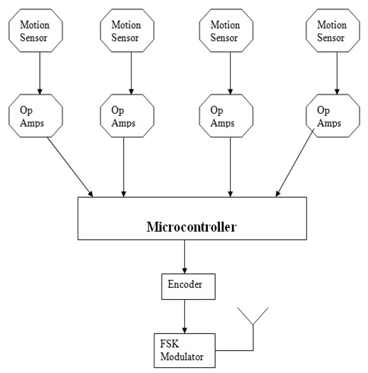
The top portion of the block diagram consist of the Passive IR Sensor that detects the invisible IR radiations of the any living object and generates a weak (small) signal which goes to the OPAMP for amplification. The OPAMP hereby, amplify the signal, makes it readable to the microcontroller and then microcontroller generates a code corresponding to the sensor detection.

As the code is generated which looks like something as 0000 0000 0001, 0000 0000 0011, etc is transmitted to the encoder. The code is transmitted to the encoder at every 1ms to the FSK Transceiver section for modulation of signal and transmission of signal wirelessly 
Each passive IR sensor senses and generates the signal at different port of the microcontroller and it then depends on the microcontroller to generate a unique corresponding code related to the passive IR sensor detection. Multiple passive IR sensors can detect a single object and generate codes which in result generates signal on the multiple ports of the microcontroller. Under such situation, it depends on the microcontroller to take the input of multiple sensors at a time and then decide the correct location of the object on the basis of received data.
2.2 Receiving Section
 Automatic Gun Targeting System2
2.2.1 Working of Receiver section

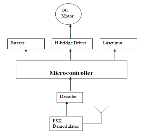
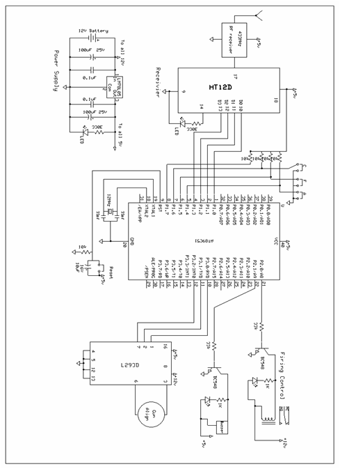
The receiver contains FSK transceiver, Microcontroller, DC motor, Firing Laser gun, H- bridge function, Buzzer Alarm and the decoder IC. The signal transmitted via transmitter is received by the FSK receiver, demodulated by a demodulator and then the signal is decoded by a decoder IC. Then the s/g is transmitted to the microcontroller and microcontroller retains the code transmitted by a transmitter and performs the function accordingly.

The signal received and code regenerates is called obtained code. The format of the obtained code is the 11110001, 11110101, 11110011 etc. Each code regenerated is destined to perform some target function. It depends on the code, how much degree will the motor rotate and targets itself to the object location and then, as the targeting function is completed, the buzzer module activates and buzzer alarm system activates that alarm everyone present into the watch tower.

As the buzzer system gets activated, after very small delay, the firing control system gets activated, and laser gun starts firing over the destined location. The fire lasts until the sensor stops sensing the IR radiations. It is a complete destruction program of the discovered living object near the border area range.

The rotation can vary accordingly to the sensation of the sensors as the code transmitted will rapidly changes. The transmitter and receiver can be at 200m from each other. If more distant, receiver will create problem in the reception of code which is an extremely important part of the program.

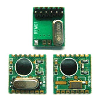
The transmitter and receiver works on 443 MHz frequency.

Chapter 3

Circuit Diagrams

3.1 Transmitter Section
Shown in circuit diagram tab 1.

3.1.1 Description of Transmitting Module Circuit Diagram

Describing this section includes some sub-sections as the module is divided in sub-sections. Particularly there are 4 sections in this transmitter module as discussed.
3.1.1.1 Sensor Module
The module is the primary module of the project. This module includes the passive IR sensors foe sensing any living object in its range defined. Under this, 4 sensors are planted over the border to sense any motion near the border and alert the watch tower for the motion. The diagrammatic structue is explained as:

Sensor Module

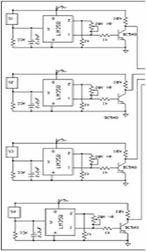
Here the broader view of the sensor module is provided. The passive IR sensors are labeled as S1, S2, S3 and S4. In this, initially each sensor has the O/P of 1 so when no sensor will sense, the combined o/p reaching at the microcontroller is 1111. As soon as any sensor detects the object, its O/P becomes 0 and microcontroller generates a code corresponding to the O/p of the sensor. Now how the sensors generate signal 5v or 0v, for that a sensor model is discussed in brief.

AGTS5

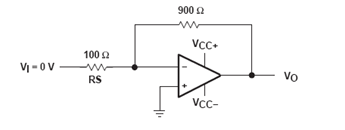
Here above, the magnified version of the sensor is shown. In this LM358 is an OPAMP IC used to amplify the small signal generated by the sensor S4 on detection of the object. The amplified s/g is applied to the transistor BC548 and the transistor conducts. So O/P is connected to the ground and so O/P becomes 0.

Here we have used the resistors R(f) of 20K and R(i) of 1K.

 V(o/p)/Vin = 1 + R(f)/R(i)

3.1.1.2 Microcontroller Code Generation


3.2 Receiver Section

3.2.1 Description of Receiving Module Circuit Diagram

Shown in circuit diagram tab 2.

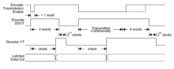
Here, microcontroller will receive the s/g generated by sensors on port P1.0, P1.1, P1.2, P1.3 and ports P1.4 – P1.7 will always remain on high status. So the code generated is 11110001, 11110011 etc. Taking the signals from the sensors, microcontroller generates the code corresponding to the sensor O/P on the port P2.0, P2.1, P2.2, P2.3. The code generated can be 1000, 1100, 1110 etc. Once generated, this code is transmitted over to the encoder, encoder encodes it and transmits it to the FSK Transceiver and FSK transceiver transmits the code to the receiver in the watch tower. 

Receiving Module consists of the Firing Control, Decoder, buzzer Alarm System, DC Motor Targeting system, Microcontroller, relay and FSK Transceiver. Under receiving module, there are various sections named above are explained as:

3.2.1.1 Microcontroller Generating Obtained Code

As the Microcontroller receives the decoded version of the transmitted code, it generates the 8bit code known as Obtained Code. It’s according to the obtained code, the rotation angle of the motor is decided in the targeted system and firing and buzzer alarm controllers will get turn on. The figures are shown below:

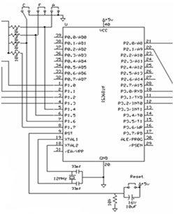
Here in the above Figure, code transmitted by Transmitter is received by the microcontroller on the ports P1.0, P1.1, P1.2, and P1.3. As explain before, Ports 1,4- ports 1.7 are always 1, so obtained code is 11110001, 11110011 same as sent by the microcontroller on the transmitting side.

The Logic behind each unique code is programmed before and the actions are pre-decided accordingly to the code received. Hence, when the code is receiver, it determines the angle by which the motor has to rotate which is a part of the Targeting System. Also the delay between firing and buzzer alarm is also decided according to the code.

3.2.1.2 Mechanism behind the DC Motor Targeting System

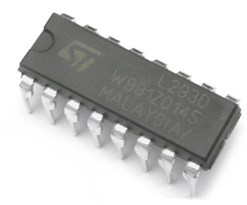
The angle rotation of the DC Motor depends on the code received on the microcontroller. The mechanism is the simple H-Bridge design of the DC Motor as shown:

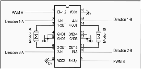
Here, the port 3.0 of t he microcontroller is connected to the Pin 1 of the IC. This pin is the enable pin, so port 3.0 of microcontroller will always remain in the +5v status.

Pin 3.1 of the microcontroller is connected to the Pin 2 of the IC and pin 3.2 is connected to the Pin 7 of the IC. The DC motor is connected to the pin 3 and pin 6 as shown.

Now the motor will follow the table below accordingly to the code received on the microcontroller:

AGTS12

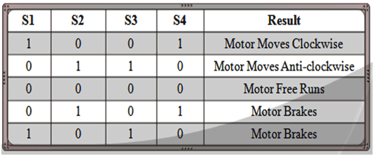
The above table shows the direction of the motor in which it will run. The motor can run clock wise, anti clock wise or free runs. The H-bridge structure for motor is shown as:

AGTS13

Now as per the figure, and the table, the motor will rotate clock wise when s1 and s4 are connected as motor will be on 12V, but when, all S1, S2, S3 and S4 are 0, no voltage is applied on the motor, hence motor will be running freely.

When S2 and S3 will be on, again motor will get the 12V supply but now, it will be reversed than before and hence, the motor will rotate anti-clockwise.

The basic and the main role here is of delay, it means for how much time the motor will rotate to attain the particular degree of rotation. Such thing we will attain with the following procedure:

1.)    Discover the RPM (Rotations per minute) of the motor. This is the value of how much rotations motor take in 60 seconds.

2.)    Discovering RPM, let 100rpm, motor will take 36000 degree rotation in 60 sec.

3.)    Now, if we want the motor to rotate 10 degree to find certain target, .0166 sec or 16.66 ms . Now, we will provide a delay of 16 ms for a motor to rotate so that we can attain the rotation of 10 degree.

This was the basic operation of Targeting System to attain the target. Now, how to attain such operation using Microcontroller. For that referring Fig: 3.5. In this figure, Ports P3.0, P3.1 and P3.2 are connected to the Motor driving IC L293D directly. As shown in Fig 3.6, P3.0 will always be 1 to enable the L293D IC. Then if it is required to move motor clockwise. We will put P3.1 as 1 and P 3.2 as 0 which will make motor rotate clock-wise and reverse action must be taken for anticlockwise rotation.

3.2.1.3 Buzzer Alarm System

The basic purpose of the buzzer alarm system is to alert the watch tower before firing the detected object. As there is manual operation provided in the project, hence if required, the firing can be halt and automation of the project can be manually controlled. Under the usage of project in small scale such as in home security purposes, the basic operation of the buzzer is to alert for the intrusion of an unwanted IR radiating obstacle.

Now for understanding the basic circuitry and working of the buzzer, have a look on the zoomed version of the Buzzer Alarm module.

Buzzer Alarm System

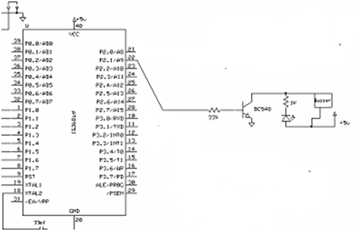
As we can see in this fig. , Pin 2.1 of a microcontroller is directly connected to the transistor of the Buzzer Alarm module. Here, when the object is detected and targeted, then the next step is to alert others using the Buzzer Alarm.

Normally, the base of the transistor is Low, so it will not conduct but as the microcontroller will provide P2.1 in high state, the base of the transistor will become high and then, transistor will begin to conduct. Now first we will discuss the operation when P2.1 is 0 because no object is detected, then we will discuss what will be the scenario when the object will be detected.

1) When no object is detected by sensors, P2.1 will remain on 0. Transistor will be on the Low state. There will be 5V supply on both sides of the buzzer as transistor is off. So buzzer will be quiet.

2) As the object is detected, the Pin 2.1 of the microcontroller will become high after the object is targeted. As the Pin will provide 1, the base of the transistor will become high and the transistor will start to conduct. Then the voltage across the buzzer system will become 12V.

3) As soon as the 12V is formed across the Buzzer Alarm system, the Buzzer will start to blow.

This is how the buzzer alarm system will continue to work as soon as the object is detected by the sensors on the transmitter section.

3.2.1.4 Firing Control System

The firing control system controls bullet fire unless the sensor detects any motion within the specified border range. To completely understand the system of the system of firing control, we should refer the figure below.

Firing Control System

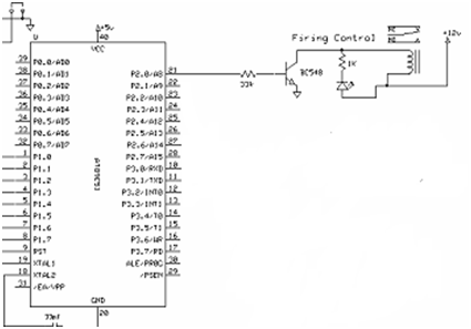
Taking a look on the Fig: 3.9, we can see that microcontroller Port 2.0 is connected to the firing control module. Here, the trigger of the gun is replaced by the relay switch for automation in firing.

As seen, from above there can be 2 cases i.e. when the Port P 2.0 is 0 and other when the Port P 2.0 is high. Below the both cases are discussed thoroughly.

1) When the port 2.0 of the microcontroller is 0, then the transistor connected to it, its base will be low and hence the transistor will not conduct. When this happens, the voltage around the magnetic coil will be 0V hence there will be no magnetism left. So the relay will not be connected and the gun will not fire.

2) When the port 2.0 will be high on the object detection by the sensors, the transistor base will become high and the transistor will conduct. When this occurs the voltage of 12V will be developed across the magnetic coil, and the coil will be magnetized. Due to this, the iron strip will be attracted and joined to the lower portion of the conducting part in relay and hence the switch will get on.

3) As soon as the switch will get on, the firing starts unless the object is completely destroyed or the sensor stops sensing IR radiation.

This was the working of the Transmitter and Receiver module and the functioning of the CKT Diagram and the step by step procedure of the working of the project. There are numerous number of components used in the project which will be discussed later in this report

Chapter 4

Hardware Used

This section describes the list of hardware used in the completion of the project. The list contains all major and minor hardware used in the project and also the detailed description of each component is discussed in this section

List of Components used

Microcontroller AT89C51
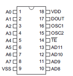
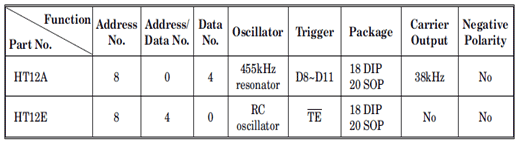
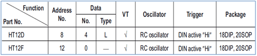
HT12E Encoder IC

 HT12D Decoder IC

Passive IR Sensor Module

Resistors 1K, 20K, 33K, 10K, 330E

Capacitors 2.2uF, 0.1uF, 100uF, 10uF
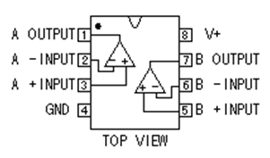
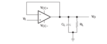
OP-AMP IC LM358

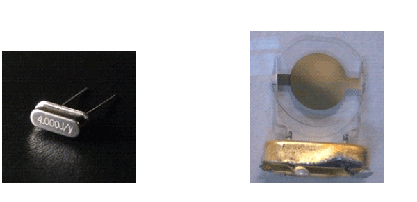
Crystal Oscillator 12MHz

Diodes IN4007

Switch

IC 7805

FSK Transceiver Module

Transistor BC548

Laser Toy Gun

L293D IC

Buzzer Alarm

DC Motor

The above shown figure is of 8051 based microcontroller AT89C51. The microcontroller is used in this project on both transmitter and the receiver section. Following are discussed the characteristics and the specifications of the microcontroller.

4.2.1 Specification:

1) `High-performance, Low-power AVR® 8-bit Microcontroller.

2)  32 programmable I/O Lines.

3)  Operating Voltage

4)  4.5 – 5.5V for AT89C51.

5) 4K Bytes of In-System Self-Programmable Flash.

6)  Master/Slave SPI Serial Interface to program.

7) Two 16 bit Timers and Counters.

8)  Six Interrupt Sources.

4.2.2 Characteristics:

Ø Pins P0.0 – P0.7, P1.0 – P1.7, P2.0 – P2.7, P3.0 – P3.7 are the 32 pins can be programmed as both I/O pins.
Ø Master/slave Serial Peripheral Interface is supported by this microcontroller which is required for connection of :
·         Microcontroller à PC
·         Single Master Microcontroller àSingle Slave Microcontroller
·         Single Master Microcontroller à Multiple Slave Microcontrollers
Ø USART (Universal Synchronous Asynchronous Receiver Transmitter) is the connection supported by microcontroller required to connect the PC to the Microcontroller in order to see the O/P of Microcontroller on PC i.e. it simply interface PC to Microcontroller as one Microcontroller to other Microcontroller.
4.3 HT12E Encoder IC

AGTS14

4.3.1 Specifications:
1) Operating Voltage 2.4V to 12V
2)  Low Power and High noise Immunity.
3)  Minimum Transmission words are 4 words.
4)  It is 2^12 Encoder IC.
5)  The Capability to select the TE trigger enhances the application flexibility of 2^12 encoders.


4.3.2 General Description:

The 212 encoders are a series of CMOS LSIs for remote control system applications. They are capable of encoding information which consists of N address bits and 12_N data bits. Each address/data input can be set to one of the two logic states. The programmed addresses/data are transmitted together with the header bits via an RF or an infrared transmission medium upon receipt of a trigger signal.
The capability to select a TE trigger on the HT12E or a DATA trigger on the HT12A further enhances the application flexibility of the 2^12 series of encoders. The HT12A additionally provides a 38 kHz carrier for infrared systems.

In the above diagram, as we can see the transmission timing for IC, it shows that:
Once the TE is enabled or this pin is low, Encoder O/P transmits 4 words.
If the Pin TE is enabled or low for long, data will continuously transmit till the pin is again high. Data transmits minimum 4 words after this pin comes high.
4.4 HT12D Decoder IC
 4.4.1 Specifications:
1) Operating Voltage 2.4V to 12V
2)  Low Power and High noise Immunity.
3)  Minimum Transmission words are 4 words.
4)  Capable of decoding 12bits of information.
5)  The Capability to select the TE trigger enhances the application flexibility of 2^12 decoders.
6)  Easy interface with RF or IR transmission medium.
4.4.2 General Description:
The 212 decoders are a series of CMOS LSIs for remote control system applications. They are paired with Holtek’s 2^12 series of encoders. For proper operation, a pair of encoder/decoder with the same number of addresses and data format should be chosen. The decoders receive serial addresses and data from a programmed 2^12 series of encoders that are transmitted by a carrier using an RF or an IR transmission medium. They compare the serial input data three times continuously with their local addresses.If no error or unmatched codes are found, the input data codes are decoded and then transferred to the output pins. The VT pin also goes high to indicate a valid transmission. The 2^12 series of decoders are capable of decoding information’s that consist of N bits of address and 12_N bits of data. Of this series, the HT12D is arranged to provide 8 address bits and 4 data bits, and HT12F is used to decode 12 bits of address information.

In the above diagram, as we can see the transmission timing for IC, it shows that:
Once the TE is enabled or this pin is low, Encoder O/P transmits 4 words.
If the Pin TE is enabled or low for long, data will continuously transmit till the pin is again high. Data transmits minimum 4 words after this pin comes high.
4.5 Passive IR Sensor Module
Passive Infrared sensor (PIR sensor) is an electronic device that measures infrared (IR) light radiating from objects in its field of view. PIR sensors are often used in the construction of PIR-based motion detectors. Apparent motion is detected when an infrared source with one temperature, such as a human, passes in front of an infrared source with another temperature, such as a wall.
All objects emit what is known as black body radiation. It is usually infrared radiation that is invisible to the human eye but can be detected by electronic devices designed for such a purpose. The term passive in this instance means that the PIR device does not emit an infrared beam but merely passively accepts incoming infrared radiation. “Infra” meaning below our ability to detect it visually, and “Red” because this color represents the lowest energy level that our eyes can sense before it becomes invisible. Thus, infrared means below the energy level of the color red, and applies to many sources of invisible energy.
We have utilizes that concept in our final year project to make a very creative project “Sensor based automatic gun targeting system for boarder area”. This project is designed for Border security area. It can be also be used for any Ultra secured area where no one is allowed to enter.
4.5.1 Specifications:
1) Supply current: DC5V-20V(can design DC 3V-24V )
2) Current drain :< 50uA
3) Voltage Output: High/Low level signal 3.3V
4) High sensitivity
5) Operation Temperature: -15degree – 70 degree
6) Infrared sensor: Low noise, High Sensitivity
4.6 FSK Transceiver Module

The above shown is the FSK Transceiver module that is required here for transmission of the signal of the sensors and code from the transmitter section to the receiver section. This FSK Module has the following specifications:
 4.6.1 Specifications:
1)  Used on bands 315MHz, 433MHz, 868MHz
2)  High data rate up to 115.2kbps with FSK modulation
3)  16 bits FIFO
4)  2.2V-5.4V power supply
5)  Support SPI interface
6)  Automatic antenna tuning
4.6.2 Description:
1) Bands 315MHz, 433MHz and 868MHz are the bands used for the unlicensed transmissions for the short range devices. 315MHz is one of the unlicensed bands used in USA. Similarly, 433MHz and 868MHz are also unlicensed bands used for short range transmission.
2) Antenna embedded in the module is not needed to be tuned manually. It supports automatic tuning of the antenna between transmitter and receiver.
3) It uses 16 bit First In First Out (FIFO) system for transmission.
4) Maximum range of the module is approximately 200m. Transmission will be successful if the distance is less than or equal to 200m.
5) It provides fast transmission with high data rate up to 115.2Kbps for transmission.
6) Operates on voltages less than or equal to 5V hence support microcontroller.
4.7 L293D IC
4.7.1 Specifications:
4.7.2 Description:
The L293 and L293D are quadruple high-current half-H drivers. The L293 is designed to provide bidirectional drive currents of up to 1 A at voltages from 4.5 V to 36 V. The L293D is designed to provide bidirectional drive currents of up to 600-mA at voltages from 4.5 V to 36 V.
Both devices are designed to drive inductive loads such as relays, solenoids, dc and bipolar stepping motors, as well as other high-current/high-voltage loads in positive-supply applications.


4.8 Crystal Oscillator

A crystal oscillator is an electronic circuit that uses the mechanical resonance of a vibrating crystal of piezoelectric material to create an electrical signal with a very precise frequency. This frequency is commonly used to keep track of time, to provide a stable clock signal for digital integrated circuits, and to stabilize frequencies for radio transmitters.

When a crystal of quartz is properly cut and mounted, it can be made to distort in an electric field by applying a voltage to an electrode near or on the crystal. This property is known as piezoelectricity. When the field is removed, the quartz will generate an electric field as it returns to its previous shape, and this can generate a voltage. The result is that a quartz crystal behaves like a circuit composed of an inductor, capacitor and resistor, with a precise resonant frequency. 
Almost any object made of an elastic material could be used like a crystal, with appropriate transducers, since all objects have natural resonant frequencies of vibration. For example, steel is very elastic and has a high speed of sound. It was often used in mechanical filters before quartz. The resonant frequency depends on size, shape, elasticity, and the speed of sound in the material. High-frequency crystals are typically cut in the shape of a simple, rectangular plate. Low-frequency crystals, such as those used in digital watches, are typically cut in the shape of a tuning fork. For applications not needing very precise timing, a low-cost ceramic resonator is often used in place of a quartz crystal.
Quartz timing crystals are manufactured for frequencies from a few tens of kilohertz to tens of megahertz. More than two billion (2×10⁹) crystals are manufactured annually. Most are small devices for consumer devices such as wristwatches, clocks, radios, computers, and cellophanes. Quartz crystals are also found inside test and measurement equipment, such as counters, signal generators, and oscilloscopes.
Quartz has the further advantage that its elastic constants and its size change in such a way that the frequency dependence on temperature can be very low. The specific characteristics will depend on the mode of vibration and the angle at which the quartz is cut (relative to its crystallographic axes).

A quartz crystal can be modeled as an electrical network with low impedance (series) and a high impedance (parallel) resonance point spaced closely together.
4.9 Buzzer
A buzzer or beeper is a signaling device, usually electronic, typically used in automobiles, household appliances such as a microwave oven, or game shows. 

It most commonly consists of a number of switches or sensors connected to a control unit that determines if and which button was pushed or a preset time has lapsed, and usually illuminates a light on the appropriate button or control panel, and sounds a warning in the form of a continuous or intermittent buzzing or beeping sound. Initially this device was based on an electromechanical system which was identical to an electric bell without the metal gong (which makes the ringing noise). Often these units were anchored to a wall or ceiling and used the ceiling or wall as a sounding board. Another implementation with some AC-connected devices was to implement a circuit to make the AC current into a noise loud enough to drive a loudspeaker and hook this circuit up to a cheap 8-ohm speaker. Nowadays, it is more popular to use a ceramic-based piezoelectric sounder like a Son alert which makes a high-pitched tone. Usually these were hooked up to “driver” circuits which varied the pitch of the sound or pulse the sound on and off.
In game shows it is also known as a “lockout system” because when one person signals (“buzzes in”), all others are locked out from signaling. Several game shows have large buzzer buttons which are identified as “plungers”.
The word “buzzer” comes from the rasping noise that buzzers made when they were electromechanical devices, operated from stepped-down AC line voltage at 50 or 60 cycles. Other sounds commonly used to indicate that a button has been pressed are a ring or a beep.
Thus we can say that buzzer is equivalent to
    OSCILLATOR + SPEAKER = BUZZER
4.10 LM358 OP-AMP IC

4.10.1 Specifications:
1) Wide Supply Range: 3V to 32V
2) Low Supply-Current Drain
3) Low Input Bias and Offset Parameters:
4) Differential Input Voltage Range Equal to  Maximum-Rated Supply Voltage is 32 V  (26 V for LM2904)
5) Open-Loop Differential Voltage Amplification 100 V/m
4.10.2 Description:
These devices consist of two independent, high-gain, frequency-compensated operational amplifiers designed to operate from a single supply over a wide range of voltages. Operation from split supplies also is possible if the difference between the two supplies is 3 V to 32 V (3 V to 26 V for the LM2904).
The low supply-current drain is independent of the magnitude of the supply voltage. Applications include transducer amplifiers, dc amplification blocks, and all the conventional operational amplifier circuits that now can be implemented more easily in single-supply-voltage systems. For example, these devices can be operated directly from the standard 5V supply used in digital systems.

4.11 Diode
A diode is a semiconductor device which allows current to flow through it in only one direction. Although a transistor is also a semiconductor device, it does not operate the way a diode does. A diode is specifically made to allow current to flow through it in only one direction. Some ways in which the diode can be used are listed here.
1) A diode can be used as a rectifier that converts AC (Alternating Current) to DC (Direct Current) for a power supply device.
2) Diodes can be used to separate the signal from radio frequencies.
3) Diodes can be used as an on/off switch that controls current.

This symbol diode1 is used to indicate a diode in a circuit diagram. The meaning of the symbol is (Anode) diode1 (Cathode). Current flows from the anode side to the cathode side.
Although all diodes operate with the same general principle, there are different types suited to different applications.
4.12 Capacitors
4.12.1 Block Capacitors
Capacitors with fixed values (the so called block-capacitors) consist of two thin metal plates (these are called “electrodes” or sometimes called the “foil”), separated by a thin insulating material such as plastic. The most commonly used material for the “plates” is aluminum, while the common materials used for insulator include paper, ceramic, mica, etc after which the capacitors get named. A number of different block-capacitors are shown in the photo below. A symbol for a capacitor is in the upper right corner of the image.
4.12.2 Electrolytic Capacitors
Aluminum is used for the electrodes by using a thin oxidization membrane.
Large values of capacitance can be obtained in comparison with the size of the capacitor, because the dielectric used is very thin.
Electrolytic capacitors represent the special type of capacitors with fixed capacity value. Thanks to special construction, they can have exceptionally high capacity, ranging from one to several thousand µF. They are most frequently used in circuits for filtering; however they also have other purposes.
Electrolytic capacitors are polarized components, meaning they have positive and negative leads, which is very important when connecting it to a circuit. The positive lead or pin has to be connected to the point with a higher positive voltage than the negative lead. If it is connected in reverse the insulating layer inside the capacitor will be “dissolved” and the capacitor will be permanently damaged.
Explosion may also occur if capacitor is connected to voltage that exceeds its working voltage. In order to prevent such instances, one of the capacitor’s connectors is very clearly marked with a + or -, while the working voltage is printed on the case. Several models of electrolytic capacitors, as well as their symbols, are shown on the picture below.

Chapter 5
Project Hardware
5.1 Transmitter Section

5.2 Receiver Section


Chapter 6

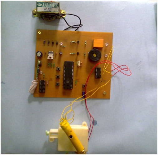
Software Used And Programming

6.1 Software Used
The Software Used for programming the 8051 microcontroller AT89C51 is Kiel Microvision 3 .The software is capable to program the microcontroller and then generate the .hex file which is the hardware programming assembly language file. The file generates is applied to the microcontroller to function as specified in the file. Below are the steps how to program the microcontroller using Kiel Microvision 3.
1) Install evaluation version of Kiel Microvision 3 into the computer. Install the specific serial drivers for the connectivity from the PC to the PCB
2) Open Kiel Microvision 3, it supports the programming in C language. Select appropriate settings related to the specified Microcontroller and then a window of program editing pops out.
3) Write the specified logic into the window in C language.
4) To embed that logic into the microcontroller, a hardware file .hex file is required to be generated
5) Go to Run>Generate .hex file and click on it to generate the .hex code of the specified C code.
6) As the .hex code is generated, embed it to the microcontroller to program it using Kiel.
7) Once code embedded to microcontroller, switch the controller on and it will function as per the embedded code.
6.2 Coding Logic and Code
The basic logic is to first sense the O/P of the sensors Placed at the Border area, generate the code corresponding to each probability of detection that can occur, once a unique code generated, and transmit it using Encoder and FSK transmitter.
On the receiver side, receive the modulated code, demodulate it, and then decode it, program receiver microcontroller to obtain the sent code known as “obtained Code”. Receiver microcontroller will react according to the unique code obtained.
6.2.1 Program
Basically the programming is divided into two sections, transmitter section and receiver section.As there are two microcontrollers used, one for transmitting the sensor radiation and another for reception of the codes sent by transmitter microcontroller and act according to code. The codes for the various locations are predefined corresponding to each location and gun will rotate as per the received code.
6.2.1.1 Transmitter section
The program is for the transmitting microcontroller.
If P1 = 11111110;
{
P2=0001;
Delay 5ms;
P2 = 0000;
Delay 5ms;
P2 = 0000;
}
If P1 = 11111101;
{
P2 = 0010;
Delay 5ms;
P2 = 0000;
Delay 5ms;
P2 = 0000;
}
If P1 = 11111011;
{
P2 = 0100;
Delay 5ms;
P2 = 0000;
Delay 5ms;
P2 = 0000;
}
If P1 = 11110111;
{
P2 = 1000;
Delay 5ms;
P2 = 0000;
Delay 5ms;
P2 = 0000;
 6.2.1.2 Receiver section
The logic implemented in receiver section is :
If P1 = 11110001;
{
P3.0 = 1;
P3.1 = 1;
P3.2 = 0;
P2.0 = 1;
Delay 16ms;               */ rotation of motor is 20degree/*
P2.0 = 0;
P2.1 = 1;
}
If P1 = 11110010;
{
P3.0 = 1;
P3.1 = 1;
P3.2 = 0;
P2.0 = 1;
Delay 16*2ms;       */ rotation of motor is 20degree/*
P2.0 = 0;
P2.1 = 1;
}
If P1 = 11110100;
{
P3.0 = 1;
P3.1 = 1;
P3.2 = 0;
P2.0 = 1;
Delay 16*3ms;               */ rotation of motor is 30degree/*
P2.0 = 0;
P2.1 = 1;
}
If P1 = 11111000;
{
P3.0 = 1;
P3.1 = 1;
P3.2 = 0;
P2.0 = 1;
Delay 16*4ms;              */ rotation of motor is 30degree/*
P2.0 = 0;
P2.1 = 1;
}
Chapter 77.1   Future Enhancements
There are certain future enhancements that can be done to the project as the project will become more accurate and developed with the future advanced technologies. The following lists some of the basic enhancements and usage that can be implemented on the project.
1) Sensor Based automatic system can be scaled according to usage:
·         At Large Scale it can be used at Border Area, Huge factories and industries.
·         At small scale, can be used for domestic purposes as home security etc.
2)   Area coverage for security can be increased by increasing the code length of the generated code.
3)   For fast response, speed control concept can be used to increase the targeting speed for the gun.
4)   Advancements in sensors can enable the system to more accurately detect any living/non living object over the restricted area.
5)   More accurate clock systems should be provided to target more accurately.
 
7.2   Drawbacks/Improvements
There are certain present facts in the project that can be improved. The following lists those facts:
 
1) Complexity of Coding increases as the code length increases to enhance the area coverage capability in Sensor Based automatic alarming and targeting system.
2)   Microcontroller clocks are not highly accurate enough to correctly provide the delay to the system and motors so targets can be missed some times due to inaccurate rotation of motors.
7.3    Conclusion
The basic idea is implemented specifically for the border area, but can be modified and could be used in any of the security requirements on scaling of cost and complexity. The basic requirement of the idea is the programming skill, as the security increases, program complexity increases.
For the border area, PIR sensors take the accurate IR data, to which the gun needs to be pointed, so better resolution is provided by allotting more number of codes per area. The system can be more accurate by using one master microprocessor controlling several slave microcontrollers. This architecture will be more accurate.
The cost of the system is reasonable; range can be varied as per requirement by setting sensors. The project is reasonably accurate but will perform better under manual assistance as the basic thinking of the project is taken by working with human but not alone taking responsibility of the complete security.
There are certain future improvements that should be taken into account for further improvement of the system.


Project Source Code


Circuit Diagrams

Automatic-Gun-targeting-System-Transmitter
Automatic-Gun-targeting-System-Receiver


Filed Under: Electronic Projects
Tagged With: automatic gun, gun, targeting
 

Questions related to this article?
👉Ask and discuss on EDAboard.com and Electro-Tech-Online.com forums.


Tell Us What You Think!! Cancel reply

You must be logged in to post a comment.

HAVE A QUESTION?

Have a technical question about an article or other engineering questions? Check out our engineering forums EDABoard.com and Electro-Tech-Online.com where you can get those questions asked and answered by your peers!


Featured Tutorials

  • Designing Gate Driver Circuit and Switching Mechanism for Modified Sine Wave Inverter – (Part 9/17)
  • Completing Modified Sine Wave Inverter Design with Full Bridge Circuit and Step Up Transformer – (Part 10/17)
  • Designing an Offline UPS – Part (12 /17)
  • How to reduce Switching Time of a Relay – (Part 15/17)
  • Testing MOSFET – (Part 16/17)
  • Driving High Side MOSFET using Bootstrap Circuitry – (Part 17/17)

Stay Up To Date

Newsletter Signup

Sign up and receive our weekly newsletter for latest Tech articles, Electronics Projects, Tutorial series and other insightful tech content.

EE Training Center Classrooms

EE Classrooms

Recent Articles

  • Renesas to demonstrate first working silicon based on the Arm Cortex-M85 processor
  • STMicroelectronics releases first automotive IMU with embedded machine learning
  • Infineon offers DC-DC controller for full LED headlamps without a microcontroller
  • Vishay launches new high-precision, thin-film wraparound chip resistor
  • STMicroelectronics’ common-mode filters ensure signal integrity in serial interfaces

Most Popular

5G 555 timer circuit 8051 ai Arduino atmega16 automotive avr dc motor display Electronic Part Electronic Parts Fujitsu ic infineontechnologies integratedcircuit Intel IoT ir lcd ldr led maximintegratedproducts microchip microchiptechnology Microchip Technology microcontroller microcontrollers mosfet motor powermanagement Raspberry Pi remote renesaselectronics renesaselectronicscorporation Research samsung semiconductor sensor software STMicroelectronics switch Technology vishayintertechnology wireless

RSS EDABOARD.com Discussions

  • IC wirebonding question
  • PS4 chip replacement not going to plan
  • Level shifter for differential oscillator
  • Voltage reference level - how to choose?
  • Boost converter, 3W...shielded or unshielded inductor?

RSS Electro-Tech-Online.com Discussions

  • software PWM
  • Background of Members Here
  • Audio equalizer
  • SPI Questions
  • Dog Scarer
Engineers Garage
  • Analog IC TIps
  • Connector Tips
  • DesignFast
  • EDABoard Forums
  • EE World Online
  • Electro-Tech-Online Forums
  • Microcontroller Tips
  • Power Electronic Tips
  • Sensor Tips
  • Test and Measurement Tips
  • 5G Technology World
  • About Us
  • Contact Us
  • Advertise

Copyright © 2022 WTWH Media LLC. All Rights Reserved. The material on this site may not be reproduced, distributed, transmitted, cached or otherwise used, except with the prior written permission of WTWH Media
Privacy Policy | Advertising | About Us

Search Engineers Garage

  • Projects and Tutorials
    • Electronic Projects
      • 8051
      • Arduino
      • ARM
      • AVR
      • PIC
      • Raspberry pi
      • STM32
    • Tutorials
    • Circuit Design
    • Project Videos
    • Components
  • Articles
    • Tech Articles
    • Insight
    • Invention Stories
    • How to
    • What Is
  • News
    • Electronic Products News
    • DIY Reviews
    • Guest Post
  • Forums
    • EDABoard.com
    • Electro-Tech-Online
    • EG Forum Archive
  • Digi-Key Store
    • Cables, Wires
    • Connectors, Interconnect
    • Discrete
    • Electromechanical
    • Embedded Computers
    • Enclosures, Hardware, Office
    • Integrated Circuits (ICs)
    • Isolators
    • LED/Optoelectronics
    • Passive
    • Power, Circuit Protection
    • Programmers
    • RF, Wireless
    • Semiconductors
    • Sensors, Transducers
    • Test Products
    • Tools
  • EE Resources
    • DesignFast
    • LEAP Awards
    • Oscilloscope Product Finder
    • White Papers
    • Webinars
  • EE Learning Center
  • Women in Engineering