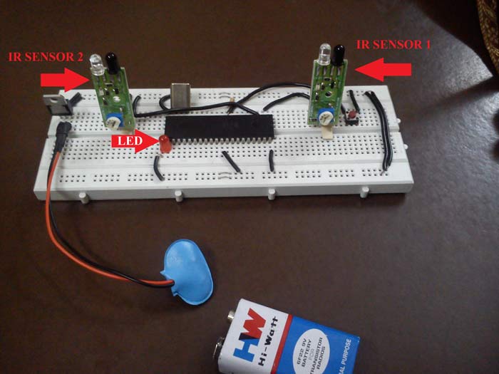
Fig. 1: Image of IR Sensor used in 8051 Microcontroller based Automatic Room Lights

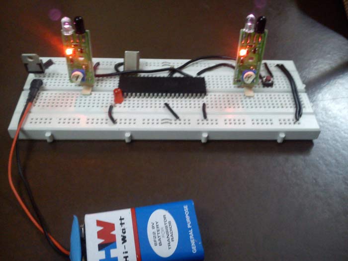
Fig. 2: Prototype of 8051 Microcontroller based Automatic Room Lights
Requirements:
· 2 x IR sensor module
· AT89S52 (8051 microcontroller by ATMEL corp.)
· Crystal (11.0592 MHz)
· LED (or a relay controlled room lighting system)
Pre-requisite:
About IR sensor module:
IR (Infrared Rays) sensors work on infrared waves, the module comprises of one IR led (transmitter) and one photodiode (receiver). Module consists of 3 pins namely GND, VCC (+5V) and SIG. SIG pin provides the TTL value based on the reference voltage set. It also consists of a potentiometer which can be adjusted to vary the reference voltage hence varying its range and accuracy.
This module provides a HIGH (+5V) signal when a voltage greater than reference voltage is generated and a LOW (0V) signal when it is lower than reference voltage.
These modules also have an onboard LED which glows off when an object is detected.
Description
Description:
When an object moves into the room it passes through IR sensor 1 first and then IR sensor 2, this makes the microcontroller understand that something has moved into the room. In this situation it makes the LED to glow.
On the other hand when the last object moves out of the room it has to pass through IR sensor 2 first and then IR sensor 1, this situation helps the microcontroller to understand that no one is present in the room now, thus it glows off the LED.
In the coding part, I have used a variable “count” to count the number of objects present in the room. Count increments itself by one for every entry and decrements by one for every exit.
So when “count==0” i.e. no one is present in the room, the LED glows OFF
.
There should be a gap of minimum 1 second between every consecutive entry/exit. This is needed to ensure the accuracy of the system.
DELAY.H (user defined header file) has been used here to provide time delay in order of milliseconds according to the TIMERS in AT89S52.
IR sensors 1 and 2 are connected to PIN P1.1 and P1.2 respectively.
The LED is connected to PIN P2.0.
A reset button is connected to PIN 9 which shall be pressed in case anything goes wrong.
The IC 7805 voltage regulator provides a step down from 9V to 5V (ideal voltage for AT89S52)
The Crystal provides the desired 11.0592 MHz frequency for the microcontroller to work upon.
Applications:
This system can be used to automatically control the lightings of a room to conserve electricity.
To practically implement this idea, just connect a relay to the pin where led is connected right now, this relay will further control the AC operated devices like tub lights, fans, etc.
Add-ons:
To make it a more user friendly system connect a 16×2 LCD with microcontroller and display the number of objects present in the room by simply feeding the “count” value to the LCD.
Project Source Code
###
// Coding (MAIN): #include<reg51.h> #include<delay.h> sbit in=P1^1; sbit out=P1^2; sbit LED=P2^0; void main() { int count=0; in=out=1; ////// declaring ‘in’ and ‘out’ as input LED=0; while(1) { if(in==1) { while(!out){} count++; LED=1; delay_msec(1000); } if(out==1 && count) { while(!in){} count--; delay_msec(1000); if(!count) LED=0; } } } // Coding (delay.h): void delay_msec(int time) { int i=0; while(i<time) { TMOD=0x10; TH1=0xfc; TL1=0x66; TR1=1; while(TF1==0); TR1=0; TF1=0; i++; } }###
Circuit Diagrams
Filed Under: Electronic Projects


Questions related to this article?
👉Ask and discuss on Electro-Tech-Online.com and EDAboard.com forums.
Tell Us What You Think!!
You must be logged in to post a comment.