Water level controllers are quite common nowadays. This circuit is based on popularly used IC555 IC. Water level controller circuits have these advantages: Most the circuit only display the amount of water present in circuit, but this circuit will "on" and "off" the motor according to the level of water present in tank.
It will not automatically stop the motor when tank is fill but it will "on" the motor when water in tank reaches below a specific point. It can be easily installed in over headed tanks because of less components used in circuits. It prevents the wastage of water due to over flow of tank. Can be operated with the help of 12V battery or adaptors (converts 230V AC to 12V DC) readily available in markets.
Description
555 timer is a commonly used IC for generating accurate time pulses. If is 8 pin IC commonly used in modes –
1. Astable mode – In this mode, frequency and duty cycle are controlled by two external resistors and a capacitor. Astable 555 is very commonly used for generating time delays and pulses.
2. Monostable mode- In this mode time delay of the pulses can be precisely controlled by an external resistor and a capacitor.
Pin diagram of NE555 timer is shown below-
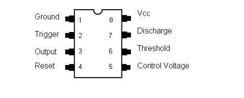
Fig. 1: Pin Diagram of NE555 timer
Assemble the circuit properly as shown in circuit diagram. Place the sensor carefully in tank. Use good quality of sensors made from non-corrosive material. And connect the sensor to the circuit at appropriate terminal like sensor terminal H at the bottom of the tank, L terminal above the lower terminal H and then place the M terminal at the top of tank. After you have properly installed the sensors in the over headed tank connect the power supply. Now your circuit is ready to use.
Working
Working
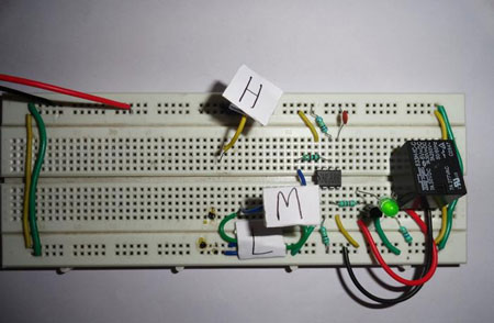
Fig. 2: Prototype of Circuit on Breadboard showing working of Automatic Water Level Controller
Working of automatic water level controller circuit is self -explanatory. As we have kept H terminal at the bottom of the tank, when water level falls below L terminal timer IC is triggered at pin 2, because of this output pin 3 goes high and energizes the relay and motor connected to it become “on”. And motor starts to fill the tank.
Now the motor remains “on” even when the level of water crosses sensor L terminal. But when water in the tank touches terminal M, NE555 timer is retriggered with the help of pin 6 as a result output pin 3 goes low. And the relay de-energizes because of that motor connected at the output become “off”.
The motor remains “off” until water level falls below sensor M. But motor will start again when water in the tank falls below sensor L. This cycle is repeated every time to “on” and “off” the motor according to the level of water present in tank so there is no need to worry about the water in over headed tank.
Video
Circuit Diagrams
Filed Under: Electronic Projects

Questions related to this article?
👉Ask and discuss on EDAboard.com and Electro-Tech-Online.com forums.
Tell Us What You Think!!
You must be logged in to post a comment.