Engineers Garage

  • Projects and Tutorials
    • Circuit Design
    • Electronic Projects
      • 8051
      • Arduino
      • ARM
      • AVR
      • PIC
      • Raspberry pi
      • STM32
    • Tutorials
    • Components
  • Contributions
  • Articles
    • EG Blogs
    • Insight
    • Invention Stories
    • How to
  • What Is
  • Forums
    • EG Forum Archive
    • EDABoard.com
    • Electro-Tech-Online
  • Digi-Key Store
    • Cables, Wires
    • Connectors, Interconnect
    • Discrete
    • Electromechanical
    • Embedded Computers
    • Enclosures, Hardware, Office
    • Integrated Circuits (ICs)
    • Isolators
    • LED/Optoelectronics
    • Passive
    • Power, Circuit Protection
    • Programmers
    • RF, Wireless
    • Semiconductors
    • Sensors, Transducers
    • Test Products
    • Tools
  • News
    • EE Design News
    • DIY Reviews
    • Guest Post
    • Sponsored Content
  • EE Resources
    • DesignFast
    • LEAP Awards
    • Oscilloscope Product Finder
    • White Papers
    • Webinars
  • EE Classrooms
    • Grid Infrastructure
    • Aerospace & Defense
    • Building Automation
    • Power Delivery
    • Factory Automation
    • Motor Drives
    • Medical Technology
  • Video

Waveform Generation using AVR Microcontroller (Atmega16) Timers- (Part 16/46)

July 7, 2010 By Ashutosh Bhatt

At times we come across applications or situations wherein we need to generate square waves with the microcontroller. The square wave can be generated by programming a pin which toggles between 0 and 1 with a certain time delay. Alternatively, the inbuilt feature of AVR timers can be used in square wave generation. The advantage of using AVR timers in wave form generation is that the output pin toggles automatically when the timer condition are fulfilled. This article focuses on usage of AVR timer for simple square wave generation.


There are four specified pins in ATmega16 for waveform generation. Each pin can be operated by their corresponding timer only. The following table provides information about it.
 
Pin Numbers in ATmega16 for waveform generation
Fig. 2: Pin Numbers in ATmega16 for waveform generation
 
Modes in Timers:
The AVR Timers work in different modes of operation. There are following modes of operation:
            1. Normal mode
            2. Clear timer on Compare (CTC) match mode
            3. Phase Correct PWM mode
            4. Fast PWM mode
Delay generation using Normal and CTC mode has been described in previous articles. These two modes are also used in square wave form generation. Phase correct PWM and Fast PWM modes are used for PWM generation.
 
Wave form generation:
It is better to use CTC mode instead of Normal mode because in CTC mode, frequency can be easily adjusted. ?
When the Timer is triggered, register TCNTn counts the value constantly as timer started. Each timer has an OCRn (Output Compare Register), which is continuously compared with TCNTn register.  In CTC mode whenever match occurs, OCFn (Output Compare Flag) will set to 1. If continuous wave form generation is required, OCFn must be reset again. Alternatively, if OCIEn (Output Compare interrupt) and Global interrupt flags in SREG are set, OCFn will reset automatically after interrupt execution.
 
In the earlier article, Timer register TCCR0 is explained. The bits WGM0 [1:0] are programmed to select waveform generation mode. The following table shows the combination of bits to select modes of operation:

Bit Value of WGM0 to select waveform generation mode in AVR

Fig. 3: Bit Value of WGM0 to select waveform generation mode in AVR


The Register TCCR0 also consists COM0 [1:0] bits. These bits are used to select functionality of OC0 pin. Following table shows function of COM 0[1:0]:

Bit Value of COM0 to select functionality of OC0 pin in AVR

Fig. 5: Bit Value of COM0 to select functionality of OC0 pin in AVR

 
Objective- To generate square wave form of 5 KHz frequency by using timer 0.
Calculation for frequency
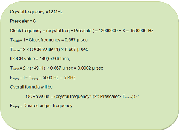
Equation For Frequency Calculation of Square Wave
Fig. 5: Equation For Frequency Calculation of Square Wave
Programming steps:
1. Select CTC mode by programming WGM0 [1:0] bit.
2. Program COM0 [1:0] bits and select “toggle OC0 if compare match”.
3. Set OC0 (PB3) pin as output pin.
4. Set OCIE0 bit of TIMSK register.
5. Enable global interrupt by “sei ()” command.
 
Circuit description:
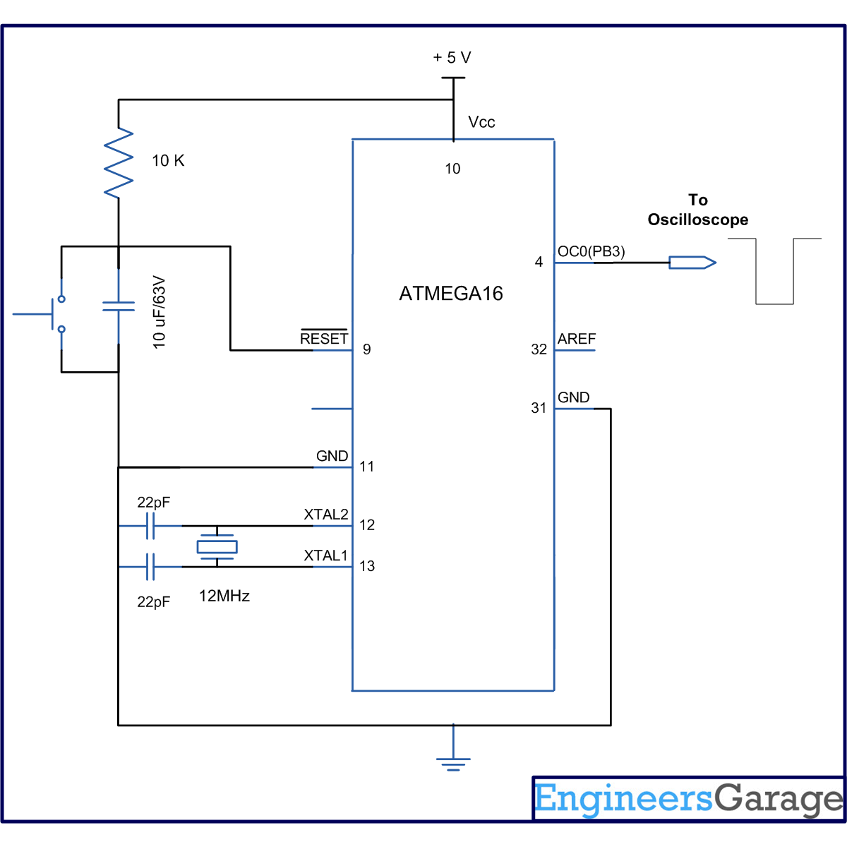
The connection of ATmega16 for this experiment is shown in circuit diagram. Since timer0 is used, hence the OC0 pin is connected to C.R.O to observe wave form. 
 
Output wave form:

The following picture shows the output wave form which is received on CRO. The measured frequency of wave is 5 KHz.
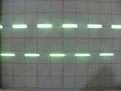
Output Square waveform on CRO using AVR Timer

Fig. 6: Output Square waveform on CRO using AVR Timer


Project Source Code

###


// Program to Generate waveform using AVR Microcontroller (Atmega16) Timers
#include<avr/io.h>
#include<util/delay.h>
#include<avr/interrupt.h>
void t0_init(void);
 
#define FREQ 12000000 // crsytal freqeuncy
#define PRECSALER 8
#define F_OUT 5000 // output frequency
#define OCR0_VALUE ((((FREQ/2)/PRECSALER)/F_OUT)-1)  
int main()
{
t0_init(); // timer initialize
sei(); // enable global interrupts
while(1);
}
 
void t0_init()
{
// WGM0[1:0]= 10, for CTC mode
// COM0[1:0]= 01, to toggle OC0 on compare match
// CS0[2:0] =010. for prescaler 8
 
TCCR0=(1<<WGM01)|(1<<COM00)|(1<<CS01);
DDRB|=(1<<PB3); // select as output pin 
TIMSK|=(1<<OCIE0); //enable output compare interrupt
}
 
ISR(TIMER0_COMP_vect) // interrupt subroutine
{
OCR0=(uint8_t)OCR0_VALUE; //put OCR value
}
 

###


Circuit Diagrams

Circuit-Diagram-of-Waveform-Generation-using-AVR-Microcontroller-Atmega16-Timers

Project Components

  • ATmega16

Project Video

Related Articles Read More >

Electronic Voting Machine using Internal EEPROM of AVR
LCD Scrolling Display Module using AVR controller and 16x2 alphanumeric LCD display setup on breadboard
LCD Scrolling Display Module- (Part 30/46)
Wrting Simple Boot-Loader code for AVR microcontroller in C to Initialize peripherals circuit set up on breadboard
How To Write a Simple Bootloader For AVR In C language- (Part 35/46)
How To Use SPM To load Application from EEPROM
How To Use SPM To load Application from EEPROM- (Part 34/46)

Stay Up To Date

Newsletter Signup

Popular Posts

Making blinking pattern of leds with 8051 microcontroller
properties of inductors
Basic Electronics 19 – Properties of inductors
GLCD 128×64 graphical lcd(GLCD) interfacing with 8051(89c51,89c52) microcontroller
Stm32f103 microcontroller controlling stepper motor by A4988 stepper motor driver module

EE Training Center Classrooms

“ee
“ee

Recent Articles

  • Renesas Electronics secures Bluetooth 5 connections with 32-bit RX23W MCU
  • iBASE introduces signaturePro 12-Port video wall signage player with outstanding capabilities
  • Microcontroller Project: STM32 low power modes analysis
  • Fujitsu starts shipping supercomputer Fugaku
  • RPi Python Programming 03 – Raspberry Pi as Linux System
Engineers Garage
  • Analog IC TIps
  • Connector Tips
  • DesignFast
  • EDABoard Forums
  • EE World Online
  • Electro-Tech-Online Forums
  • Microcontroller Tips
  • Power Electronic Tips
  • Sensor Tips
  • Test and Measurement Tips
  • About Us
  • Contact Us
  • Advertise

Copyright © 2019 WTWH Media LLC. All Rights Reserved. The material on this site may not be reproduced, distributed, transmitted, cached or otherwise used, except with the prior written permission of WTWH Media
Privacy Policy | Advertising | About Us

Search Engineers Garage

  • Projects and Tutorials
    • Circuit Design
    • Electronic Projects
      • 8051
      • Arduino
      • ARM
      • AVR
      • PIC
      • Raspberry pi
      • STM32
    • Tutorials
    • Components
  • Contributions
  • Articles
    • EG Blogs
    • Insight
    • Invention Stories
    • How to
  • What Is
  • Forums
    • EG Forum Archive
    • EDABoard.com
    • Electro-Tech-Online
  • Digi-Key Store
    • Cables, Wires
    • Connectors, Interconnect
    • Discrete
    • Electromechanical
    • Embedded Computers
    • Enclosures, Hardware, Office
    • Integrated Circuits (ICs)
    • Isolators
    • LED/Optoelectronics
    • Passive
    • Power, Circuit Protection
    • Programmers
    • RF, Wireless
    • Semiconductors
    • Sensors, Transducers
    • Test Products
    • Tools
  • News
    • EE Design News
    • DIY Reviews
    • Guest Post
    • Sponsored Content
  • EE Resources
    • DesignFast
    • LEAP Awards
    • Oscilloscope Product Finder
    • White Papers
    • Webinars
  • EE Classrooms
    • Grid Infrastructure
    • Aerospace & Defense
    • Building Automation
    • Power Delivery
    • Factory Automation
    • Motor Drives
    • Medical Technology
  • Video