Battery level indicator will let you know the status of battery of a device just by glowing the number of LED's. For example four LED's are glowing means battery capacity is 40 percent.
You can use this battery level indicator circuit with your inverter or with your car battery; it will give you indication about your battery status. So before your battery dies you can recharge it. Advantage of this circuit is it does not require power supply; it will take power supply from the battery of the device itself.
[[wysiwyg_imageupload:10520:]]
Fig. 1: Prototype of Battery Level Indicator Circuit on Breadboard
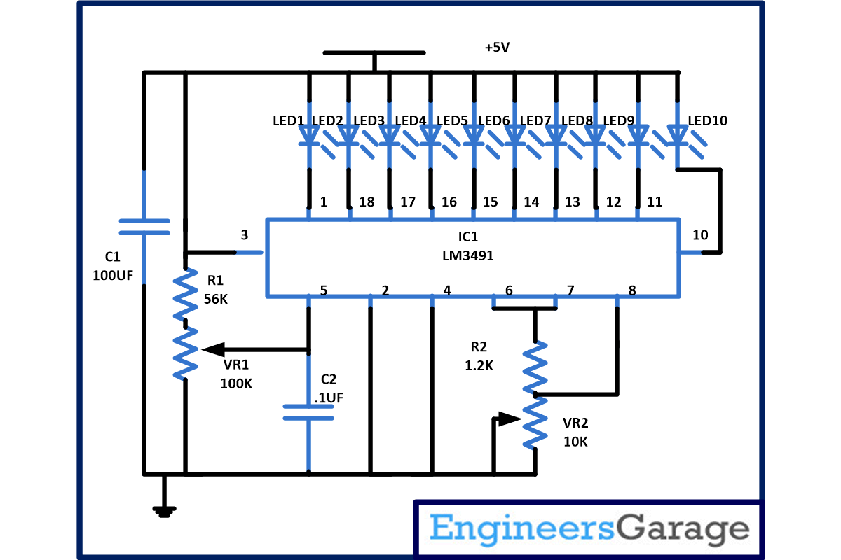
This simple battery level indicator circuit is based on single IC LM3914 with few more discrete components. LM3914 is a monolithic integrated circuit which senses the analog voltage and derives 10 LED’s providing a linear analog display.
Advantage of IC LM3914-
1. In this user can easily select the dot or bar graph display just by changing a single pin.
2. This IC can drive LED’s, LCD or vacuum fluorescent display.
3. You can cascade more IC’s up to 100 steps.
4. This IC can also work on 3V power supply.
5. In this we do not require resistor with the LED’s because current drive to LED’s is regulated and programmed.
6. It will support wide temperature range from 0 degree to +70 degree Celsius.
Working of Circuit-
For calibrating the circuit, apply the power supply and adjusts VR1 so that LED1 just start glowing. Now, increase the input voltage in steps of 1.2V and see LED2 will glow in 2.4V and similarly increase the voltage in steps of 1.2V and LED3 will glow and so on. Following table will show the voltage level when different LED will glow –
|
Highest no. LED on |
Color |
Vout |
|
10 |
Green |
12 |
|
9 |
Red |
10.8 |
|
8 |
Green |
9.6 |
|
7 |
Red |
8.4 |
|
6 |
Blue |
7.2 |
|
5 |
Red |
6 |
|
4 |
Blue |
4.8 |
|
3 |
Red |
3.6 |
|
2 |
Yellow |
2.4 |
|
1 |
Red |
1.2 |
If above phenomenon is happening your circuit is ready is use. Connect it to voltage from any battery to be tested at the input which will become power source for the circuit. And now by seeing the number of LED’s glowing you can easily calculate the status.
You can also connect different color LED for obtaining the status like connect RED LED’s as it is the sign of danger (LED 1 to LED3) which will indicate that that voltage level is less than 40 percentage and need to be taken care. Similarly connect yellow LED’s (LED4 to LED6) this will indicate battery capacity of 40 to 70 percent and remaining you can use Green LED.
If you want the change the dot display to bar display just incorporate following changes-
1. For Bar graph display- Connect pin 9 directly to pin 3(supply voltage pin)
2. For dot display- Leave the pin 9 (mode selector pin) open.
And if you want to cascade more LM 3914 IC than connect pin 9 of first IC to pin1 of next LM3914
Continue connecting pin 9 of lower input drivers to pin 1 of higher input drivers for 30, 40, or more LED displays. And the last LM3914 IC pin 9 should be connected to pin 11 of previous IC with20K resistor in parallel with LED9. This can be seen in circuit shown below-

Fig. 2: Pin Diagram of LM3914 IC
Circuit Diagrams
Project Components
Project Video
Filed Under: Electronic Projects
Filed Under: Electronic Projects


Questions related to this article?
👉Ask and discuss on EDAboard.com and Electro-Tech-Online.com forums.
Tell Us What You Think!!
You must be logged in to post a comment.