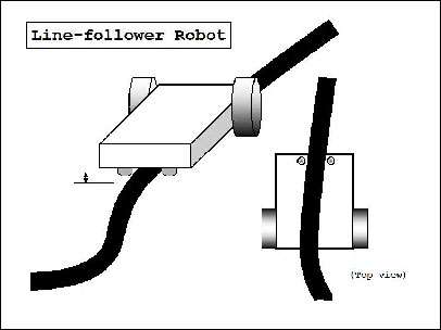
This simple bot is designed to be able to follow a black line on the ground without getting off the line too much. The bot has two sensors installed underneath the front part of the body, and two DC motors drive wheels moving forward. A circuit inside takes an input signal from two sensors and controls the speed of wheels’ rotation. The control is done in such a way that when a sensor senses a black line, the motor slows down or even stops. Then the difference of rotation speed makes it possible to make turns. For instance, in the figure on the right, if the sensor somehow senses a black line, the wheel on that side slows down and the bot will make a right turn.
PROBLEM DEFINITION
In the industry carriers are required to carry products from one manufacturing plant to another which are usually in different buildings or separate blocks. Conventionally, carts or trucks were used with human drivers. Unreliability and inefficiency in this part of the assembly line formed the weakest link. The project is to automate this sector, using carts to follow a line instead of laying railway tracks which are both costly and an inconvenience.
APPLICATION
• Industrial automated equipment carriers
• Entertainment and small household applications.
• Automated cars.
• Tour guides in museums and other similar applications.
• Second wave robotic reconnaissance operations.
LIMITATIONS
• Calibration is difficult, and it is not easy to set a perfect value.
• The steering mechanism is not easily implemented in huge vehicles and Impossible for non-electric vehicles (petrol powered).
• Few curves are not made efficiently, and must be avoided.
• Lack of a four wheel drive, makes it not suitable for a rough terrain.
• Lack of speed control makes the bot unstable at times.
DESIGN AND IMPLEMENTATION
BLOCK DIAGRAM
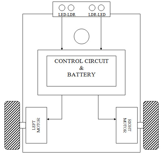
It is consist of three parts.
1) Sensor circuit
2) Control circuit
3) Steering system or Motor drive
Sensor circuit:
It is made using LDR (light dependent resistor) and LED. The LED is light emitting diode, it act as constant light source. The LDR is sensor which resistance is change according to light fall on the surface. In the dark, the resistance of the LDR is very high, typically around 1M ohm. In bright light it is low, typically 1K ohm. Using this characteristic of LDR We made black line follower sensor. In our circuit we used two LDR and two LED which act as constant light source.
Control circuit:
It is made using NE-555 timer IC. The 555 timer is an integrated circuit (chip) implementing a variety of timer and multivibrator applications. Here we are used as simple flip-flop operation.
The output of NE-555 is set or reset according to voltage at pin -4 of NE-555 IC.
The pin connections of the 555 timer are as follows:
1) Ground. Connect this to ground. Remember to connect all grounds in a circuit together.
2) Trigger. A short low (less than 1/3 Vcc) pulse on the trigger starts the timer. By connecting this to ground we “turn on” the 555 timer.
3) Output. During a timing interval, the output stays at +VCC. Can source up to 200ma.
4) Reset. Forces pin 3 low if pulled to ground.
5) Control. Can be used to adjust threshold trigger voltage. Not used in our applications. Connect to ground with a .01uF cap to eliminate supply noise from Vcc.
6) Threshold. When threshold crosses above 2/3 Vcc timing interval ends.
7) Discharge. Connects to ground when output goes low. Controls timing.
7) Vcc. Power supply. Typical range 4.5v to 16v.
Steering system or Motor drive:
The differential steering system is used to turn the bot. In this system, each back wheel has a dedicated motor while the front wheels are free to rotate. To move in a straight line, both the motors are given the same voltage (same polarity). To manage a turn of different sharpness, the motor on the side of the turn required is given lesser voltage.
The differential steering system is familiar from ordinary life because it is the Arrangement used in a wheelchair. Two wheels mounted on a single axis are independently powered and
Controlled, thus providing both drive and steering. Additional passive wheels (usually casters) are provided for support. Most of us have an intuitive grasp of the basic behavior of a differential steering system. If both drive wheels turn in tandem, the bot moves in a straight line. If one wheel turns faster than the other, the bot follows a curved path. If the wheels turn at equal speed, but in opposite directions, the bot pivots.
The Differential steering model
SCHEMATIC
The schematic of the “Line following bot” is shown in the figure.
As discuss earlier Path is Follow by two LDR sensors. As shown Schematic fig. The Light Dependent Resistor and a trim pot form a voltage divider which is used to apply bias to IC-NE555. When the among two LDR one of the LDR1 on the black line, the emitted light from LED not reflected on LDR1 surface so it offer high resistance path from Vcc to reset pin so negative voltage appear at pin -4 of NE-555 so due to this it disable out put of this IC and no current flow from driver transistor so left motor or right motor is off according to sensor position .but opposite LDR2 on white background so reflected light falls on LDR2 and it offer small resistance path from Vcc to pin 4, so it enable out put and opposite side motor is turn on and bot take turn.
The turn taken by bot is depend on the which LDR reside on black line; if both LDR on white background it go straight forward direction cause of both motor is enable.
Component list:
|
SR.NO
|
Component
|
Quantity
|
|
1
|
NE-555
|
2
|
|
2
|
Resistor:
LDR
Trim port 10K
Resistor -470ohm
// -1K
|
2
2
2
2
2
|
|
3
|
LED
|
2
|
|
4
|
DC motor-6V
|
2
|
|
5
|
Transistor-2N2222A
|
2
|
|
6
|
Wheels
|
2
|
|
7
|
Battery-6V,300mA
|
1
|
|
8
|
Cardboard -7.5”X5.5”
|
1
|
|
9
|
Motor Clamp with screw
|
2
|
|
10
|
Caster wheel (front wheel)
|
1
|
|
11
|
Jumper wire
|
1mtr
|
|
12
|
PCB-2.5”X 2.5”
|
1
|
RESULT & CONCLUSION
For a test, we held our bot and we approached a white paper to sensors. Then, both wheels rotated as expected and they slowed down when either the paper moved away or sensors passed across a black line. Overall, the bot project wasn’t successful, but it was quite a fun to go through all the process. We also realized that there were many things to consider practically such as installation of motors, building up a circuit by soldering and putting all parts together. This experience hopefully would be helpful in the future work.
Filed Under: Electronic Projects

Questions related to this article?
👉Ask and discuss on Electro-Tech-Online.com and EDAboard.com forums.
Tell Us What You Think!!
You must be logged in to post a comment.