In many big bungalows, houses, rowhouses, or farmhouses, we may find an automatic GATE or automatic garage door. Such a gate or door opens automatically when the owner’s CAR arrives, and, after some time, it closes automatically. There’s no need for any gate-man (chowkidar or Gurkha) to open-close the gate or door when the car arrives.
The normal automatic gates/doors are simple in operation. They just open and close when any CAR arrives. But now, these automatic gates/doors are not as simple. Instead, they’re sophisticated and password-operated, biometric ID-operated, smart CARD (RFID) operated, or many other options.
A password operated gate/door may be found in:
- LOCKER
- House/office/shop main doors
- Locker room door in BANKs
A biometric ID operated gate/door may be found in:
- Highly secured area
- Trespassing restricted area
A smart card operated gate/door may be found in:
- Entry/exit gate of parking in MALLS/supermarket/Multiplex theatres
- Toll plaza on highways
So, here one such password-operated GATE/door is demonstrated. What’s interesting, however, is the password is not entered through a keypad. But the password is entered through the user’s smartphone. The person uses his smartphone to enter the password and open or close the GATE.
The system uses a Bluetooth-based android application in a smartphone to enter the password. There is a servo motor that operates and opens or closes the gate. The system is developed using the Bluetooth module (HC-05) and the Arduino microcontroller board. The system has also LCD screen to display various messages or warnings.
Let us first understand the system block diagram…
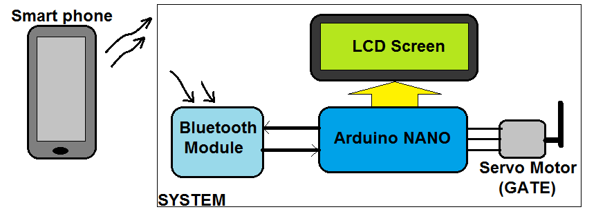
The smartphone: It’s used to send the password to the system to open the GATE. The smartphone is using an android application through which it will send the password through a built-in Bluetooth.
The Bluetooth module: It’s used to receive data (password) from a smartphone and give it serially to the Arduino NANO microcontroller.
The Arduino NANO board: It gets a password from the Bluetooth module and checks if it is correct or not. If the password is correct, it sends a signal to rotate the motor and if it is wrong gives a warning message.
The servo motor: It works as the GATE. When it moves to 90o, this means the GATE is open. When it moves to 0o, this means the GATE is closed.
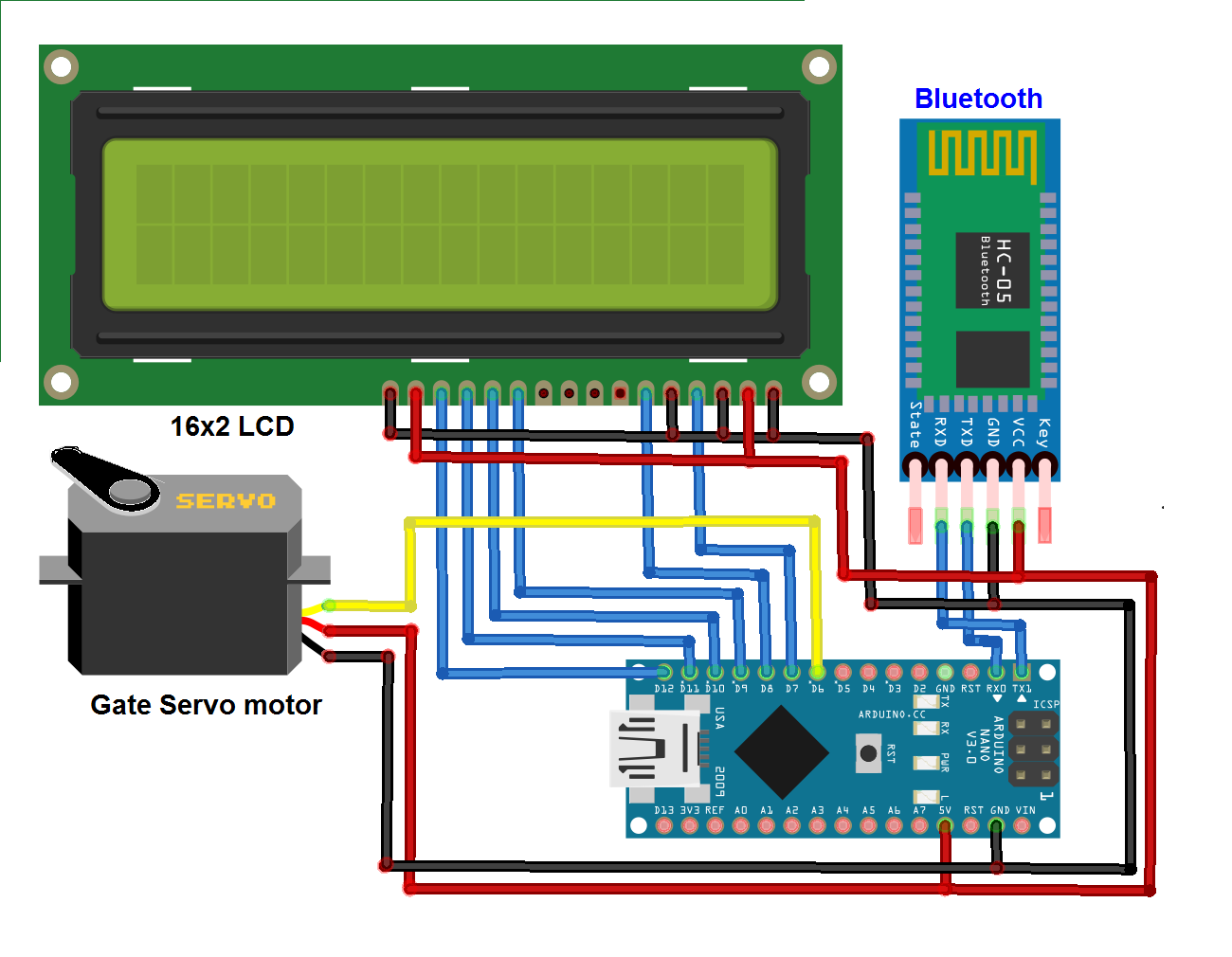
Circuit description
The major building blocks of the circuit are the Arduino NANO development board, the HC-05 Bluetooth module, the alphanumeric LCD panel, and the DC servo motor
- The servo motor operates on 5V, received from the 5V supply pin of the Arduino board. The PWM signal to the motor is given from the analog output (PWM) pin D6 from the Arduino board.
- The HC-05 module also operates on 5V, which is given from the Arduino board. It communicates with the Arduino board and the USART pins Tx-Rx. So, its Tx pin is connected with the Rx pin from the Arduino board and vice versa.
- The 16×2 alphanumeric LCD is connected in 4-bit mode with Arduino. Its 4 data pins D4-D7 are connected to the digital pins D9, D10, D11, and D12 from the Arduino board. Its two control pins Rs and En are connected with the digital pins D7 and D8, respectively.
- The LCD read/write control pin RW is connected to the ground to make it “write enable only.’ Its contrast control pin VEE is also connected to ground for full contrast.
- The LCD backlight LED is given its supply from the Arduino board.
Circuit working and operation
When the Arduino board is given supply (through 12V external supply to the Vin pin / USB cable), the complete circuit gets power and starts its operation.
- Initially, the gate is closed and the servo motor is at 0o. The Bluetooth module starts searching for any nearby device. The LCD displays the message as: “To open door enter password”
- To open the gate, one has to enter the password using a smartphone through the Bluetooth-based android application.
- The person who wants to open the gate will first open the Android application by using the Bluetooth data sending facility on his or her smartphone. This application will search and pair with the HC05 module (for pairing the first time, it is required to enter the Bluetooth passkey for the HC05 module — which is by default 1234).
- Now the person will enter the correct password that is “2468”. This password is set in the program itself during coding.
- As he or she enters the password from a smartphone, it will be sent to the HC05 module. The HC05 module will give this password to the Arduino NANO through the serial link (Tx-Rx)
- Arduino will try to match this password with the set password (that is 2468) and, if a match is found, it will send the PWM signal to the servo motor to rotate it 90o to open the GATE.
- When the GATE opens, the message is displayed on LCD as “door open.” After five seconds, Arduino will again rotate the motor to 0o and close the GATE. The LCD shows the message “door close” for two to three seconds and again it will display: “To open door enter password.”
- If the entered password is not correct, then Arduino will not rotate the motor and the GATE will not open. Arduino displays a warning message on the LCD as “wrong password.” Once again, the system will wait for the password to open the door.
- If the wrong password is entered three times, the system prohibits further entering the password. The system shows a message on LCD as “all attempts over”.
This working and operation of the circuit are as per the program embedded into the Arduino NANO microcontroller ATMega328. Now, let us see the software program for this system.
Software program
The program is written in C / C++ language using the Arduino IDE software tool. It’s also compiled and downloaded into the internal memory (FLASH) of the ATMega328 microcontroller using this same software.
Here’s the program code:
#include <LiquidCrystal.h>
#include <Servo.h>
LiquidCrystal mylcd(13,12,11,10,9,8);
char recved_digit[5];
char password[5] = “2468”;
int i=0,attempt=0;
Servo gate_servo;
void setup()
{
Serial.begin(9600);
mylcd.begin(20,4);
mylcd.clear();
mylcd.print(“To open door”);
mylcd.setCursor(0,1);
mylcd.print(“Enter password”);
gate_servo.attach(6);
gate_servo.write(0);
mylcd.setCursor(0,2);
}
void loop()
{
if(Serial.available()){
if(attempt<3)
{
recved_digit[i] = Serial.read();
mylcd.print(recved_digit[i]);
delay(250);
i++;
}
}
if(i==4)
{
if(strcmp(recved_digit,password)==0)
{
mylcd.clear();
mylcd.print(“door open”);
gate_servo.write(90);
delay(5000);
mylcd.clear();
mylcd.print(“door close”);
gate_servo.write(0);
delay(2000);
mylcd.clear();
mylcd.print(“To open door”);
mylcd.setCursor(0,1);
mylcd.print(“Enter password”);
mylcd.setCursor(0,2);
}
else
{
mylcd.setCursor(0,3);
mylcd.print(“wrong password”);
delay(3000);
mylcd.setCursor(0,3);
mylcd.print(” “);
mylcd.setCursor(0,2);
attempt++;
}
i=0;
}
if(attempt==3)
{
mylcd.setCursor(0,3);
mylcd.print(“all attempts ovr”);
}
}
Filed Under: Featured, Microcontroller Projects

Questions related to this article?
👉Ask and discuss on Electro-Tech-Online.com and EDAboard.com forums.
Tell Us What You Think!!
You must be logged in to post a comment.