In the previous tutorial, we learned how to use the applications of the Matrix LED scrolling message boards. This included how to send a message or notice to display on such a board by using a laptop or desktop PC.
In this article, we’re going to learn how to send that message from a smartphone using a Bluetooth application. This message will be continuously displayed and scrolled on the notice board.
This means whenever a user wants to display a new message, he or she can connect to the system via a smartphone using Bluetooth, type in the new message, and send it. It’s that simple.
For this project, I’ve used a readymade Matrix LED scrolling message board that’s been built using six units of an 8×8 LED block. There are a total of 384 LEDs (6x8x8). The board can receive a message as a serial input from any digital device, such as a microcontroller or a microprocessor. It accepts serial data in the 8-N-1 format with 9600 BPS.
The circuit also uses an Arduino NANO board and the Bluetooth module HC-05, which can receive a message from a user’s smartphone and send it to the Matrix LED board for display.
Circuit diagram
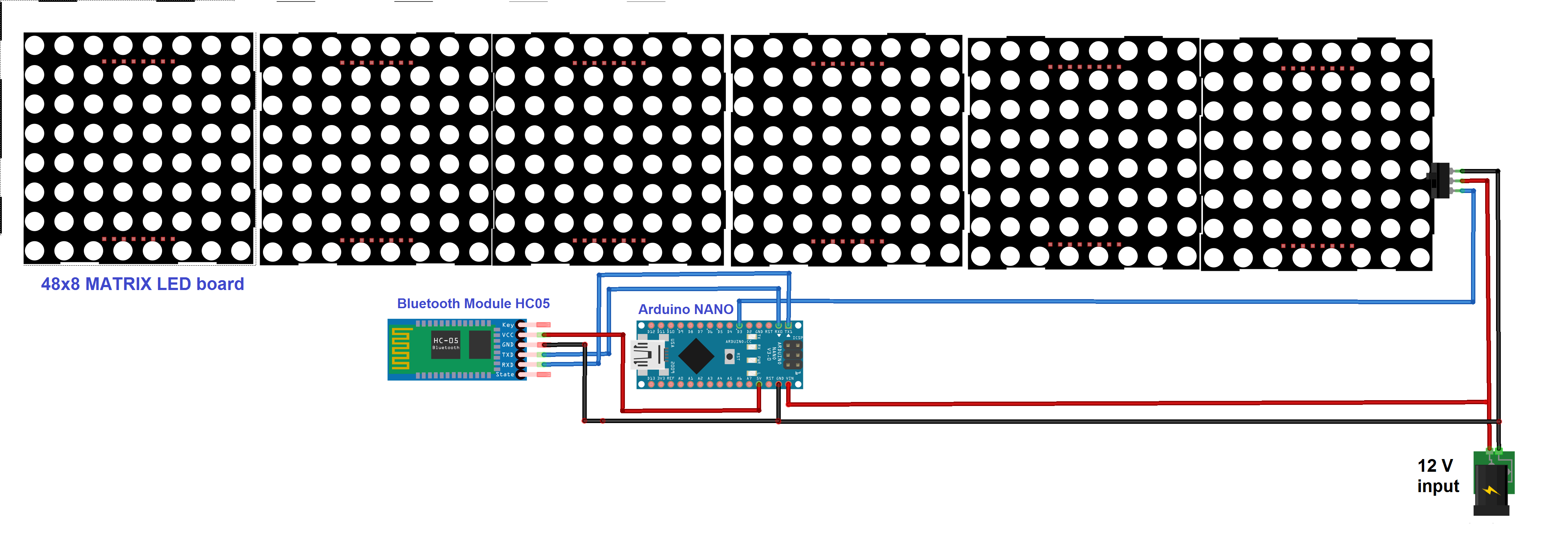
Circuit description
As shown in figure there are only three building blocks in the circuit: the scrolling message on the Matrix LED board, the Arduino NANO board, and the Bluetooth module HC-05.
Note:
- The scrolling message Matrix LED board requires three wires for interfacing the Vcc, GND, and the serial input. For the Vcc, a 12V @ 1A supply is required as an external power supply from the adapter. Its serial data input is connected with the Arduino board’s digital pin D3.
- The Bluetooth module HC-05 uses four wires for interfacing the Vcc, GND, TX, and RX. Its Vcc pin is given 5V from the Arduino board and the GND pin must connect with the common ground. Its TX and RX pins are connected with the Arduino board’s RX (D1) and TX (D0) pins, respectively.
- The Arduino board also receives a 12V input from the adapter to its Vin pin.
Circuit operation
The circuit operation for this project is simple. When the 12V supply is provided to the circuit, it will start operating. The Arduino board receives a string (message) from the HC-05 module and will pass it on to the Matrix LED board. The scrolling message will then be displayed on this board.
Note:
- Initially, the default message “EC Department, G P Jamnagar” is displayed and continuously scrolled on the board (though it’s easy to set any preferred default message).
- The user can send a message (string) through a smartphone using the Bluetooth-based application. However, to display the new message, the user first has to connect and pair its smartphone with the HC-05 module (this requires the passkey, “1234”). Make sure the module remains open.
- Type in the message on the smartphone and send it to the system via the Bluetooth application.
- This notice will be transmitted by the smartphone-connected Bluetooth and will be received by the HC-05 module. It is, then, serially given to the Arduino NANO board.
- Arduino will temporarily store the message in its internal RAM. Once the message is completely received, Arduino will send it serially to the scrolling message Matrix LED board for display.
- Arduino’s digital pin D3 works as the serial data TX pin that sends the message to the Matrix LED board.The format to send this message is:
“!_____________________message________________\r” - This means the text message to be scrolled must start with an ‘!’ and end with an ‘\r’.
- Arduino then inserts this start and end characters in the message received from the HC-05 module and sends it to the Matrix LED board.
- The matrix LED board will continuously display and scroll this message until it receives a new message.
So, every time a user wants to display a new message, he or she can send it from a Bluetooth-connected smartphone and the message will be continuously displayed and scrolled on the Matrix LED board.
Software program
#include <SoftwareSerial.h>
SoftwareSerial matrix_LED_serial(2,3);
char msg[100];
int i=0,led=2;
void setup()
{
// put your setup code here, to run once:
Serial.begin(9600);
matrix_LED_serial.begin(9600);
Serial.begin(9600);
matrix_LED_serial.print(“!EC Department G P Jamnagar\r”);
Serial.println(“Bluetooth based scrolling notice board”);
delay(5000);
Serial.println(“waiting for new notice……”);
display_notice_serial();
BT_serial.println(“send Message”);
}
void loop()
{
while(Serial.available())
{
msg[i] = Serial.read();
i++;
}
if(msg[i-1]==’\r’)
{
matrix_LED_serial.print(‘!’);
matrix_LED_serial.print(“New Notice: “);
matrix_LED_serial.print(msg);
matrix_LED_serial.print(‘\r’);
i=0;
}
}
Now, let us make this notice board a bit more realistic…and interesting.
What if every time, when a new message is displayed, the board also displays the current time and date?
This is how it’s done…
I’ve just added one more module to the circuit — the RTC DS1307 module, which is used to display the current time and date in the notice.
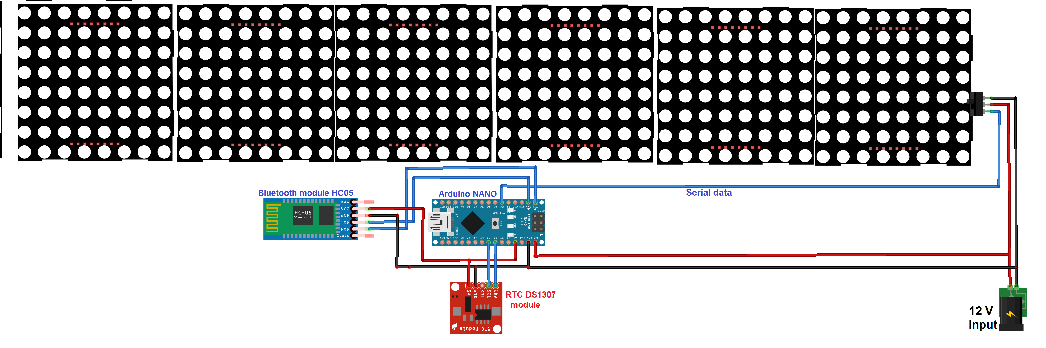
As shown in the above figure, everything remains identical except for the additional RTC module.
Note:
- The RTC module requires four wires for interfacing the Vcc, GND, SDA, and SCL. Its Vcc pin is connected with 5V from the Arduino board and the GND pin is connected to the common ground.
- The SDA and SCL pins are for the IIC/TWI communication. They’re connected with the respective Arduino SDA and SCL pins A4 and A5.
Circuit operation
- When the Arduino board receives the new notice from the HC-05 module, it will read the current date and time from the RTC module.
- Then, it will arrange the date, time, and new message in proper format and send it together to the scrolling message board.
- The format will be:
“!New Notice: Date – DD/MM/YYYY, Time-HH:MM:SS, Message-_________________\r” - Now, every new message will be date and time-stamped.
- This message will continuously scroll until a new one is received or someone resets the system.
#include <SoftwareSerial.h>
#include <Wire.h>
#include “RTClib.h”
void display_time_n_date();
SoftwareSerial matrix_LED_serial(2,3);
RTC_DS1307 rtc;
char msg[100];
int i=0,led=2;
void setup()
{
// put your setup code here, to run once:
Serial.begin(9600);
pinMode(2,OUTPUT);
digitalWrite(2,LOW);
matrix_LED_serial.begin(9600);
Serial.begin(9600);
if (! rtc.begin())
{
Serial.println(“Couldn’t find RTC”);
while (1);
}
if (! rtc.isrunning())
{
Serial.println(“RTC is NOT running!”);
}
////// use this rtc.adjust function to adjust RTC date and time
///// once (first time) only. then comment it out
//rtc.adjust(DateTime(2018, 7, 24, 22, 03, 00));
matrix_LED_serial.print(“!EC Department G P Jamnagar\r”);
matrix_LED_serial.print(250, HEX);
Serial.println(“Bluetooth and RTC based scrolling notice board”);
delay(5000);
Serial.println(“waiting for new notice……”);
display_notice_serial();
BT_serial.println(“send Message”);
}
void loop()
{
while(Serial.available())
{
msg[i] = Serial.read();
i++;
}
if(msg[i-1]==’\r’)
{
matrix_LED_serial.print(‘!’);
matrix_LED_serial.print(“New Notice: “);
display_time_n_date();
matrix_LED_serial.print(msg);
matrix_LED_serial.print(‘\r’);
i=0;
}
}
void display_time_n_date()
{
DateTime now = rtc.now();
matrix_LED_serial.print(“Date-“);
matrix_LED_serial.print(now.day());
matrix_LED_serial.print(‘/’);
matrix_LED_serial.print(now.month());
matrix_LED_serial.print(‘/’);
matrix_LED_serial.print(now.year());
matrix_LED_serial.print(“, Time-“);
matrix_LED_serial.print(now.hour());
matrix_LED_serial.print(‘:’);
matrix_LED_serial.print(now.minute());
matrix_LED_serial.print(‘:’);
matrix_LED_serial.print(now.second());
matrix_LED_serial.print(“, Message: “);
}
In next article, we’ll learn how to send a message to this board from distant place through SMS.
Filed Under: Arduino, Microcontroller Projects

Questions related to this article?
👉Ask and discuss on Electro-Tech-Online.com and EDAboard.com forums.
Tell Us What You Think!!
You must be logged in to post a comment.