Humidity is the percentage of water vapor contained in an air. It’s a very important parameter for manufacturing industries. Humidity affects almost all the products during its manufacturing process. For example, chemical, pharmaceutical, textile manufacturing industries, FMCG product manufacturing industries, packed food and dairy product manufacturing industries etc all has to take care of humidity during its manufacturing process. Even electronic component and IC (chip) manufacturing industries have to continuously monitor and control the humidity to get a precise and accurate product.
So, monitoring and controlling humidity is one of the most important tasks for all such industries. We cannot measure direct humidity but we can measure relative humidity popularly known as RH. RH (relative humidity) is the amount of water vapor in the air relative to what the air can hold. Means if air can hold total 40 gm of water vapor but it is holding only 30 gm, then RH is (30/40) × 100 = 75%. RH is always measured in %.
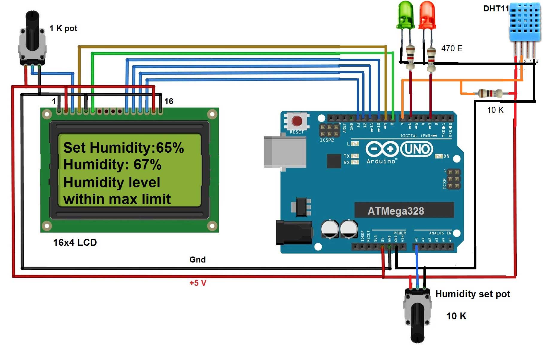
The given project measures humidity using humidity sensor and displays its value on LCD. It also compares the humidity with set humidity level and gives a message on LCD if humidity level of room is more than set level of humidity. It uses humidity sensor DHT11 (that can also measure temperature) and Arduino UNO board. The desired humidity level can be set by potentiometer from 0 to 100%. The LCD displays set humidity level and actual humidity in the room in % of RH. Two LEDs are used to indicate humidity level is within set value or above-set value.
CIRCUIT CONNECTIONS
1. The output of DHT11 pin 2 is connected to digital pin 7 or Arduino board. The pin is also pulled high by 10 K resistor. Pin 1 of DHT11 is given +5 V supply from Arduino board and pin 4 is connected to ground. Pin 3 is left unconnected.
2. LCD control pins Rs and En are connected to Arduino pins 8 and 9 respectively. One more control pin RW is connected to ground to make LCD write enable.
3. LCD data pins D4 – D7 are connected to Arduino pins 10 – 13.
4. One pot of 1K is connected to LCD to vary its contras on Vee pin. LCD backlight terminals LED+ (15) and LED- (16) are connected to 5V and ground respectively. To turn ON LED backlight of LCD.
5. Two LEDs Red and Green are connected to digital pins 3 and 6 of Arduino board as shown.
6. One pot of 10 K is connected to analog input pin A0 of Arduino board.
Here is the snap of circuit arrangements.

Fig. 1: Prototype of Arduino based Humidity controller
CIRCUIT OPERATIONS
• The pot connected to analog input pin A0 is used to set required humidity level. As pot varies, the analog input voltage at pin A0 varies from 0 to 5 V. The Arduino converts this into digital value 0 to 1023. This value is further mapped into 0 to 100%. So using pot, one can set required humidity value as 0 – 100 % RH.
• This set value of humidity is displayed on LCD as “Set humidity = XX %“ and it varies as the pot is changed.
• Arduino continuously reads humidity value from sensor and displays on LCD as “Humidity = XX %”. This value is also in the range of 0 – 100% RH. If this value is less than 2% of set humidity level then Arduino displays “Humidity is within set level”. The green LED is ON to indicate humidity level is OK.
• If humidity increases above 2% of set level the message is displayed on LCD as “humidity is above max limit”. The green LED turns OFF and red LED turns ON to indicate humidity is above max limit.
• Thus Arduino continuously senses humidity using sensor and displays it on LCD. Also, it continuously compares humidity with set level and gives LED indications.
SOFTWARE PROGRAM
Complete functionality of project is because of the program downloaded into arduino board microcontroller ATMega328. The program is the soul of the project. The program (also known as the sketch) is written and compiled in arduino IDE software tool. And it is burned (embedded) into ATMega328 using built in software programmer tool AVRISP MK-II through the USB port.
Project Source Code
###
#include "DHT.h" // header file for sensor #include <LiquidCrystal.h> // header file for LCD #define DHTPIN 7 // DHT sensor pin #define green_led 6 #define red_led 3 #define DHTTYPE DHT11 // type of sensor DHT 11 DHT dht(DHTPIN, DHTTYPE); LiquidCrystal lcd(8, 9, 10, 11, 12, 13); void setup() { pinMode(green_led, OUTPUT); // LED pins as output pinMode(red_led, OUTPUT); digitalWrite(red_led, LOW); // turn off both LEDs digitalWrite(green_led,LOW); lcd.begin(16,4); lcd.clear(); lcd.print("Set Humidity:"); // display initial text on LCD lcd.setCursor(0, 1); lcd.print("Humidity:"); dht.begin(); // initialize and start sensor } void loop() { int set_rh = analogRead(A0); // get set humidity from pot set_rh = map(set_rh,0,1023,0,99); // map value between 0 – 100% lcd.setCursor(13, 0); lcd.print(set_rh); // display value lcd.print('%'); delay(2000); // take readings after every 2 sec float rh = dht.readHumidity(); // get humidity from sensor lcd.setCursor(9, 1); lcd.print(rh); // display it on LCD lcd.print('%'); if(set_rh+2<rh) // if it’s more than 2% { lcd.setCursor(0, 2); lcd.print("Humidity level"); // display message lcd.setCursor(0, 3); lcd.print("above max limit "); digitalWrite(red_led, HIGH); // turn ON red LED digitalWrite(green_led,LOW); } else // otherwise { lcd.setCursor(0, 2); lcd.print("Humidity level"); // display message humidity is lcd.setCursor(0, 3); lcd.print("within max limit"); // normal digitalWrite(red_led, LOW); // and turn ON green LED digitalWrite(green_led,HIGH); } }###
Circuit Diagrams
Project Video
Filed Under: Electronic Projects
Filed Under: Electronic Projects

Questions related to this article?
👉Ask and discuss on EDAboard.com and Electro-Tech-Online.com forums.
Tell Us What You Think!!
You must be logged in to post a comment.